Let's look how easy it is to implement a simple cookie based language switch in the rocket web framework for the rust programming language.
Defining the language type:
In this case there will be support for Dutch and English. PartialEq is derived to be able to compare Lang items with ==.
The Default trait is implemented to define the default language:
The FromStr trait is implemented to allow creating a Lang item from a string.
The Into<&'static str> trait is added to allow the conversion in the other direction.
Finally the FromRequest trait is implemented to allow extracting the "lang" cookie from the request.
It always succeeds and falls back to the default when no cookie or an unknown language is is found.
How to use the Lang constraint on a request:
And the language switch page:
And as a cherry on the pie, let's have the language switch page automatically redirect to the referrer. First let's implement a FromRequest trait for our own Referer type:
When it finds a Referer header it uses the content, else the request is forwarded to the next handler. This means that if the request has no Referer header it is not handled, and a 404 will be returned.
Finally let's update the language switch request handler:
Pretty elegant.
A recap with all code combined and adding the missing glue:
Showing posts with label grep. Show all posts
Showing posts with label grep. Show all posts
Saturday, June 17, 2017
Monday, August 19, 2013
madparts release 1.2
It's been a few months, but finally the new madparts 1.2 release is available!
Madparts is a functional electronics footprint editor with support for the Kicad and Eagle electronics Cad programs.
Madparts is a functional electronics footprint editor with support for the Kicad and Eagle electronics Cad programs.
 |
| screenshot of madparts 1.2 running on linux/xmonad |
Highlights
KiCad support
Finally full support for importing and exporting footprints from/to KiCad is now available. madparts supports both the old .mod file format and the newer .pretty/.kicad_mod file format.
More shapes
1.2 adds support for arcs, partial circles, polygons and holes.
QtScriptEngine
Alex Schultz contributed javascript handling with QtScriptEngine instead of PyV8. This means there is one less dependency for the program making it easier to install, package and maintain. It is also faster! Thanks again Alex!
More documentation
Documentation is still sparse, but there is some more description of the supported features and code structures. Be sure to also have a look at my own private github repo of madparts footprints for more code examples.
Conclusion
If you want to give it a try, head to the website at http://madparts.org/ for more information and downloads. If you find issues or have questions, don't hesitate to email me.
The future
For madparts 1.3 a few changes are planned:
- switch to SVG based graphics rendering to get rid of the dependency on modern openGL 2.1, making the program also usable on older computers
- more documentation
- better error handling
Friday, May 31, 2013
BufferSerial: let Arduino Stream writes go in a buffer
When you have existing code that uses an Arduino Stream like "Serial" or "SoftwareSerial" data is written part by part on the serial device. Sometimes you want to collect different parts first, maybe adding something like a checksum and only then send everything on one go. By using the BufferSerial construct you can just keep the existing code, pass it the BufferSerial instead of your normal Serial and afterward use the content of the buffer, and send it as one big blob.
A simple example:
The code for BufferSerial is really simple and can be found at: https://github.com/andete/blog-stuff/tree/master/BUFSER1 .
A simple example:
uint8_t mybuffer[32];
BufferSerial bs(mybuffer, 32);
bs.print((int)42);
bs.write(' ');
bs.print(127, HEX);
bs.print("hello");

Serial.println(bs);
The code for BufferSerial is really simple and can be found at: https://github.com/andete/blog-stuff/tree/master/BUFSER1 .
Tuesday, May 28, 2013
NullSerial, a /dev/null Serial Stream for Arduino
Sometimes I use a (Software) Serial device for debugging in some AVR/Arduino code.
An easy way to disable this debugging without going through the entire code or using macros is using this simple dummy serial device instead of the real thing.
Usage example:
The full code can be downloaded at github.
An easy way to disable this debugging without going through the entire code or using macros is using this simple dummy serial device instead of the real thing.
Usage example:
#ifdef WANT_DEBUG
#include <softwareserial.h>
SoftwareSerial Debug(4, 5); // RX. TX
#else
#include "NullSerial.h"
NullSerial Debug;
#endif
NullSerial itself is this:
class NullSerial : public Stream
{
private:

public:
  // public methods
  NullSerial() {}
  ~NullSerial() {}
  void begin(long speed) {}
  bool listen() { return true; }
  void end() {}
  bool isListening() { return true; }
  bool overflow() { return false; }
  int peek() { return -1; }

  virtual size_t write(uint8_t byte) { return 0; }
  virtual int read() { return -1; }
  virtual int available() { return 0; }
  virtual void flush() {}

  size_t write(const char *str) { return 0; }
  size_t write(const uint8_t *buffer, size_t size) { return 0; }

  size_t print(const __FlashStringHelper *) { return 0; }
  size_t print(const String &) { return 0; }
  size_t print(const char[]) { return 0; }
  size_t print(char) { return 0; }
  size_t print(unsigned char, int = DEC) { return 0; }
  size_t print(int, int = DEC) { return 0; }
  size_t print(unsigned int, int = DEC) { return 0; }
  size_t print(long, int = DEC) { return 0; }
  size_t print(unsigned long, int = DEC) { return 0; }
  size_t print(double, int = 2) { return 0; }
  size_t print(const Printable&) { return 0; }

  size_t println(const __FlashStringHelper *) { return 0; }
  size_t println(const String &s) { return 0; }
  size_t println(const char[]) { return 0; }
  size_t println(char) { return 0; }
  size_t println(unsigned char, int = DEC) { return 0; }
  size_t println(int, int = DEC) { return 0; }
  size_t println(unsigned int, int = DEC) { return 0; }
  size_t println(long, int = DEC) { return 0; }
  size_t println(unsigned long, int = DEC) { return 0; }
  size_t println(double, int = 2) { return 0; }
  size_t println(const Printable&) { return 0; }
  size_t println(void) { return 0; }

  // public only for easy access by interrupt handlers
  static inline void handle_interrupt();
};
All this assumes you're not using the return values of the print/println methods.The full code can be downloaded at github.
Friday, May 24, 2013
madparts release 1.1
A new release of the madparts functional electronics footprint editor is available.
Important changes are:
Important changes are:
- py2exe simple Windows installation: just unzip the zip file and execute madparts.exe
- linux packages for madparts and pyv8 for Debian and Ubuntu i386 and x86_64
- a ton of bug-fixes
- various internal code cleanups
- simple built-in command line interface for listing of libraries and import and export of footprints
For downloads, and more details head over to the madparts.org website. As always, don't hesitate to contact me with questions or feedback at joost@madparts.org or use the github bugtracker.
The next release will normally contain support for KiCad, but I first I need to learn working with it :)
 |
| madparts running on macosx |
Tuesday, May 14, 2013
high power LED retrofit (part 4)
So the lamp is working fine. Here it is suspended to the stairs for duration testing.


So dimming works, remote control works and temperature measurement all works. For some reason Lux measurement is not working, I think I may have fried that sensor by accident.
Cabling is still somewhat of a mess, but I was thinking of sorting that out when the lamp is moved to it's final place.
Then a day passed, and I got some time to think :)
Right now there are two locations where active circuitry is located: near the lamp for temperature measurement and fan control, and near the power supply for on/off (relay), wireless, dimming and lux measurement.
These two locations are connected via a whole bunch of cables. And I'm already doing cheap wireless at one point. That is just silly!
So the next step will be creating a separate board with wireless for each of those two locations. The only wiring remaining between the two locations will be a 12V/GND cable, and of course the LED current cable.
To be continued, but somewhat further in the future as I'm working on some other things at the moment, and I want to design some proper PCBs for the next step that fit in a nice casing and such.
Sunday, May 5, 2013
high power LED retrofit (part 3)
Murphy always strikes multiple times...
It's not all bad though, while having the lamp open, I decided to improve some things.

With the help of some thick aluminium foil cut to the right size and bolted down, I get a much nicer mounting of the LED. While at it I also improved the location of the thermo-couple. It now sits all the way on top of the LED, right at the official temperature measurement point!
Speaking about temperature...

Brief testing showed this works just fine! Brief testing also immediately showed the temperature rising again rapidly!


fan speed control (PWM) fried
So Friday I accidentally hooked up the fan the wrong way and (as I found out afterwards) killed the fan PWM circuitry.
micro-controller fried
Turned out the fan speed control died "short". This also caused a power surge towards the micro-controller which also died. Strangely it still somewhat worked but when I tried to re-program that always failed. So I replaced the micro-controller for the second time, installed the boot-loader and firmware, and back to business.
Not so fast though, I first need to install a new fan.
So I open the lamp only to find out...
LED broken
I guess my crude mounting with the aluminium brackets put to much strain on the LED die and that combined with heat caused it to crack. Luckily I had a spare lying around.It's not all bad though, while having the lamp open, I decided to improve some things.
Better LED mounting

With the help of some thick aluminium foil cut to the right size and bolted down, I get a much nicer mounting of the LED. While at it I also improved the location of the thermo-couple. It now sits all the way on top of the LED, right at the official temperature measurement point!
Speaking about temperature...
LED PWM
In my early testing with the LED, I found that when driving the LED at near or full blast (800mA-1000mA) the LED got warm really fast, easily reaching 60-70 degrees Celsius.
With my testing with the whole setup, temperature stayed nice and low, peaking at about 42 degrees Celsius. What is happening there?
First thing I did was measure with the thermo-couple of my multi-meter. Exactly the same temperature. Then I measured the current provided to the LED.
Turns out exactly 330mA is provided when PWM is fully on. And I'm using 3.3V PWM... That can't be a coincidence.
The LED driver officially works on 10V PWM, but I assumed as it was dimming fine with 3.3V PWM that it also supports that. My guess is now they're just using an analog filter to convert the PWM signal to a voltage., and then interpret the Voltage on a scale from 0 to 10V.
Easily fixed though, I created a simple amplifier circuit like this:

Brief testing showed this works just fine! Brief testing also immediately showed the temperature rising again rapidly!
Other heatsink
While inside the lamp anyway, I decided to install another heat-sink:

Some more testing showed that even though the heat-sink does the job, some active (fan) cooling is still highly appropriate.
New fan

Here the new fan is spinning nicely during a test.
Cable mess
While working on the inside anyway, I got annoyed by all the cables easily blocking the fan, etc.. so I re-arranged and fixed them.
That's where the lamp is at now!
To be continued!
Click here for Part 4.
Thursday, May 2, 2013
high power LED retrofit (part2)
In this second part we're looking at the code that is going to control the LED lamp. Remark that the code discussed is the code as it is today (2/5/2013), for the latest code, go to github.
Also note that this is the code without the auto-dimming as that feature is still under test.
Also note that this is the code without the auto-dimming as that feature is still under test.
Ports & Plugs
static PortI2C bus1(1);
static LuxPlug lux_plug(bus1, 0x39);
static Port fan_port(2);
static Port temperature_port(3);
static Port relay_port(4);
Here the Jeenode ports are set up. We're using all 4 ports. Port 1 is connected to a software I2C bus, which is used by the lux_plug. Port 2 is a simple port, which we use for fan control. Port 3 is another simple port which we use for temperature control and port 4 is finally used to switch the relay.
global state
static uint8_t counter = 0;
#define DATA_MSG_SIZE 11
static uint8_t data_msg[DATA_MSG_SIZE];
Some global state. A counter which is inserted in responses to have an increasing number for testing, and a message buffer which is used for building up the response to the message that queries the system state.
LED PWM
namespace led_pwm {
  static const byte PIN = 9;
  static byte setting = 35;

  static inline void setup() {
    pinMode(PIN, OUTPUT);
    analogWrite(PIN, setting);
  }

  static inline void set_dim(const uint8_t dim) {
    setting = dim;
    analogWrite(PIN, setting);
  }
}
Pretty straightforward, using Arduino pin 9 for PWM, this is not a pin that is part of one of the Jeenode ports, but is instead available on a separate header.
fan
namespace fan {
  static const uint8_t default_pwm_setting = 35;
  static uint8_t pwm_setting = 0;
  volatile uint16_t pulse_count = 0;
  static uint16_t pulse_count_save = 0;
  static uint8_t pulse_per_second = 10;

  void pulse_interrupt() {
    ++pulse_count;
  }

  static inline void normal() {
    pwm_setting = default_pwm_setting;
    fan_port.anaWrite(pwm_setting);
  }

  static inline void setup() {
    fan_port.mode(OUTPUT);
    attachInterrupt(1, pulse_interrupt, FALLING);
    normal();
  }
  static inline void update_pulse_per_second() {
    const uint16_t l = pulse_count;
    pulse_per_second = l - pulse_count_save;
    pulse_count_save = l;
  }

  static inline void full_blast() {
    pwm_setting = 255;
    fan_port.anaWrite(pwm_setting);
  }

  static inline void off() {
    pwm_setting = 0;
    fan_port.anaWrite(pwm_setting);
  }
}
PWM handing is quite similar to the LED PWM, except here the fan_port Jeenode port is used to access the digital pin. In the setup method an interrupt handler is registered for the INT1 interrupt calling pulse_interrupt() on the falling edge. This causes pulse_count to be incremented for each pulse received from the fan. update_pulse_per_second() is then called every second to calculate a new pulse_per_second by simply looking at the difference.
temperature
namespace temperature {
  static int8_t value = 0;

  static inline void beep(const int16_t len = 100) {
    temperature_port.digiWrite(1);
    delay(len);
    temperature_port.digiWrite(0);
  }

  static inline void setup() {
    temperature_port.mode(OUTPUT);
    beep(500);
  }

  static inline void handle() {
    const int16_t t = temperature_port.anaRead();
    value = map(t, 0, 1023, 0, 330); // 10 mV/C
  }
}
Temperature is pretty straightforward. The temperature port digital pin is used to activate the buzzer on the temperature plug, the analog input pin is used to sample the temperature which is then converted from 0-1023 to 0-330 degrees Celsius.
lux
namespace lux {
  static uint16_t value = 0;

  static inline void setup() {
    lux_plug.begin();
  }

  static inline void handle() {
    lux_plug.getData();
    value = lux_plug.calcLux();
  }
}
Lux measurement is really simple, all the work is nicely hidden by the LuxPlug class.
indicator LED
namespace indicator {
  static const byte PIN = 8;

  static inline void on() {
    digitalWrite(PIN, LOW);
  }
  static inline void off() {
    digitalWrite(PIN, HIGH);
  }

  static inline void setup() {
    pinMode(PIN, OUTPUT);
    for (int8_t i = 0; i < 10; ++i) {
      on();
      delay(100);
      off();
      delay(100);
    }
  }
}
In indicator LED is connected to Arduino pin 8 as the Jeenode has no LED build-in and having some visual feedback is always handy while testing.
relay
namespace relay {

  static bool value = false;

  static inline void off() {
    relay_port.digiWrite(HIGH);
    delay(1000);
    relay_port.digiWrite(LOW);
    value = false;
  }

  static inline void on() {
    relay_port.digiWrite2(HIGH);
    delay(1000);
    relay_port.digiWrite2(LOW);
    value = true;
  }

  static inline void setup() {
    relay_port.mode(OUTPUT);
    relay_port.digiWrite(LOW);
    relay_port.mode2(OUTPUT);
    relay_port.digiWrite2(LOW);
    off();
  }
}
The relay is handled by the relay_port. Both the digital and the analog pin of that port are used as digital pins and control the on and off signals of the latching relay. The latching relay is driven by a simple breakout board connected to port 4 of the Jeenode, that just brings up the 3.3V digital signals to the 5V needed for the relay.
RF
namespace rf {
  static inline void setup() {
    // this is node 1 in net group 100 on the 868 MHz band
    rf12_initialize(1, RF12_868MHZ, 100);
  }

  static inline bool available() {
    return (rf12_recvDone() && rf12_crc == 0 && rf12_len >= 1);
  }

  static inline uint8_t command() {
    return rf12_data[0];
  }

  static inline void ack() {
    rf12_sendStart(RF12_ACK_REPLY, 0, 0);
    rf12_sendWait(1);
  }
}
The rf namespace provides just a thin wrapped around the Jeenode provided rf12 functionality. The first byte of a received packet is interpreted as a command. Packets with CRC checksum errors are not looked at.
commands
namespace commands {
  static inline void on() {
    rf::ack();
    relay::on();
  }

  static inline void off() {
    rf::ack();
    relay::off();
  }

  static inline void dim_value() {
    if (rf12_len >= 2) {
      led_pwm::set_dim(rf12_data[1]);
    }
    rf::ack();
  }

  static inline void beep() {
    rf::ack();
    temperature::beep();
  }

  static inline void query_data() {
    rf12_sendStart(RF12_ACK_REPLY, data_msg, DATA_MSG_SIZE);
    rf12_sendWait(1);
    ++counter;
  }


  static inline void handle() {
    indicator::on();
    switch (rf::command()) {
      // standard commands
      case 0: on(); break;
      case 1: off(); break;
      case 2: dim_value(); break;
      case 10: query_data(); break;
      case 11: beep(); break;
    }
    indicator::off();
  }
}
The handle() method here handles the possible commands received via RF. Just some simple dispatcher code.
taking measurements
static inline void take_measurements() {
  indicator::on();
  fan::update_pulse_per_second();
  lux::handle();
  temperature::handle();

  data_msg[0] = counter;
  data_msg[1] = relay::value;
  data_msg[2] = led_pwm::auto_mode;
  data_msg[3] = temperature::value;
  data_msg[4] = fan::pulse_per_second;
  data_msg[5] = led_pwm::setting;
  data_msg[6] = led_pwm::auto_setting;
  data_msg[7] = led_pwm::auto_calculated_pwm;
  data_msg[8] = fan::pwm_setting;
  memcpy(data_msg+9, &lux::value, 2);
  indicator::off();
}
This simple method called every second just gets new fan speed, lux and temperature measurements. They are also stored in the data_msg structure in case they are queried over RF later.
safety checks
static inline void safety_checks() {

  if (temperature::value > 50) {
    Serial.println(F("Danger, temp > 50, turning off lamp!"));
    relay::off();
    return;
  }

  if (!fan::forced) {
    if (temperature::value > 40) {
      Serial.println(F("temp > 40, fan full blast!"));
      fan::full_blast();
    } else {
       if (!relay::value && temperature::value < 30) {
         fan::off();
       } else {
         fan::normal();
       }
    }
  }

  if (fan::pulse_per_second < 20 && fan::pwm_setting > 0) {
    Serial.println(F("fan pulse not found, turning off lamp!"));
    relay::off();
    return;
  }

}
This method, also called every second, does some safety checks concerning temperature and fan speed. The lamp is turned off if the temperature raises above 50 degrees Celsius or when the fan is no longer running. When the temperature goes above 40 degrees Celsius the fan is turned fully on to provide extra cooling.
Note that the thresholds are still subject to change.
setup
void setup () {
  Serial.begin(9600);

  indicator::setup();
  rf::setup();
  lux::setup();
  temperature::setup();
  fan::setup();
  led_pwm::setup();
  relay::setup();
}
Really simple, just setting up all individual functions.
loop
void loop () {
  static int8_t loop_count = 0;

  if (rf::available()) {
    commands::handle();
    return;
  }

  ++loop_count;

  // take measurements every second
  if (loop_count % 20 == 0) {

    take_measurements();
    loop_count = 0;
    safety_checks();

  }
  delay(50);
}
Finally the main loop of the sketch. Checks for new RF messages every 50 milliseconds and updates measurements and does safety checks every 20 loops, hence every second.
That's it for a close look at the software.
To be continued later with another look at the hardware!
Click here for the next post in this series.
Wednesday, May 1, 2013
high power LED retrofit (part1)
When I got hold on an old large industrial style lamp, I immediately knew I wanted to make something cool out of it.
This picture shows the lamp with the new LED already in place, hanging from a ladder, to give an impression of the size.

I decided to make it a lamp with the following specifications:


This picture shows the lamp with the new LED already in place, hanging from a ladder, to give an impression of the size.

I decided to make it a lamp with the following specifications:
- using a modern, very high power LED for serious brightness and yet good efficiency
- fully dimmable
- optional automatic dimming with ambient light sensing
- temperature sensing and overheat protection
- passive cooling or else using a low speed inaudible fan
- remote controllable
Besides that I wanted to use mostly readily available breakout boards to minimize time spent researching sensors and writing drivers.
LED
After some research I decided to use the CREE XLamp CXA2530 which is a very modern LED with a very high brightness and great efficiency. I chose a warm-white color temperature variant.
It has some very impressive specs:
- Size: 23.85mm x 23.85mm
- Maximum drive current: 1.5A
- Maximum power: 61W
- Light output: 3000 – 5700lm
- Typical forward voltage @ 0.8 A, 85°C: 37V
- Viewing angle: 115 degrees
- Thermal resistance: 0.8 °C/W
For more details and full specifications visit the CREE website. To give you a rough idea: at 30W this LED gives light equivalent to a more then 100W incandescent lamp.
Power supply
As the LED used needs some serious power a very good power supply will be needed. It should be able to provide up to 40V at 1A, be constant current based, and would ideally support dimming out of the box.
After some research I settled on the MeanWell HLM-40H-42B which is really quite expensive but has very high efficiency, can provide the requirement voltage and current, and has dimming built-in.
Dimming works by means of a PWM signal that is provided to the module. This signal will be provided by the micro-controller. The module also supports dimming via a sense resistor.
When no dimming signal is provided the power supply is fully on. This implies that in case the PWM signal from the micro-controller disappears, the LED will be fully on. By shorting the dim connector with a 10k resistor the lamp will fall-back to a ~10% dimmed state when the micro-controller fails to provide the dimming signal. The PWM signal is strong enough to take prescedence when active.
Micro-controller
As micro-controller breakout board I'm using a JeeNode v6.

This is an Arduino compatible micro-controller board based on an Atmel atmega328p like in Arduino UNO. It comes with an on-board HopeRF RFM12B 868Mhz RF interface. The provided JeeLib software is installed as a library and provides access to 4 "ports" on the board in a convenient way.
Each port supports what is called a "plug" in the Jee-world.
I'm using two plugs and the other two ports are used directly for their pins.
Lux sensing
Lux sensing is done by means of the JeeLabs LuxPlug. This is based on a simple I2C bus lux measurement IC.

The result is a 16-bit light intensity number that can be used for automatic dimming of the lamp.
Temperature sensing
The temperature is measured near the LED die by means of a K-type thermocouple. The thermocouple signal is amplified by an AD597 IC provided by the JeeLabs Thermo Plug.

The temperature can be used by the micro-controller to shutdown the lamp in case over overheating or to control the fan speed depending on the temperature.
Fan control
Some initial testing showed that the temperature of the LED rises really fast, even with a large heat-sink attached. Some more testing showed that doing active cooling with a large fan running at a low (inaudible) speed makes a large (>10°C) difference, and a cooler LED is a happier LED with a longer lifetime.
I settled on installing a 12cm PC fan. With the sides cut of it is a perfect fit inside if the top of the lamp, sucking out air upwards.

In order to allow cables to enter the lamp from above without blocking the fan, a simple spacer is needed. The 3D-printer to the rescue! This picture also shows part of the heat-sink at the top. The heat-sink is not really ideal and I plan to use other heat-sinks for future builds.
Finally the fan is mounted and running nicely. This picture also shows the LED mounted on the case with some pieces of aluminium, some screws and some thermal paste. If you look carefully you also see the tip of the thermocouple sitting under the aluminium very near to the LED.

The fan also provides a pulse per rotation signal on another wire. This signal is connected on the pin for the INT1 interrupt facility of the micro-controller. In the interrupt handler a counter is incremented for each activation. By them sampling this counter every second I get a rough value on the rotations/second speed of the fan. If the speed drops below a certain threshold the lamp can be turned of for safety reasons.
Relay
While just fully dimming turns the lamp off, this still means that the LED power supply is powered and in case of some failure the lamp might turn on again.
To be able to fully turn of the driver a relay is inserted on the AC line before the power supply. The specific relay I'm using is a dual-pole, dual coil, latching relay.
Dual-pole means that it can switch both wires of the AC, completely disconnecting the power supply when off.
Dual coil latching means that the relay has a separate coil for turning on and for turning off. To change state one of the coils is activated for a short time only. This means the relay uses no power when active, only when changing state.
Here is the relay wired up to be integrated in the lamp setup.

An added complexity is that the relay coils operate at 5V and the micro-controller only provides 3.3V (and limited current) on the digital outputs.
As the micro-controller gets 5V in this is easily remedied by introducing two low-side N-channel switching mosfets.
The next simple (untested!) schematic shows how this could be done.

[Update: the circuit above is flawed in that the IRF540 mosfets require at least 4V and I'm providing a 3V3 signal. I replaced them by BC935 NPN BJT transistors, and removed R3 and R4]
Remote control
In order to be able to control the lamp remotely I want to make a simple remote based on the Jeelabs Jeenode Micro, and more specific the variant with the build-in boost converter that can be easily run from only one 1.5V battery.
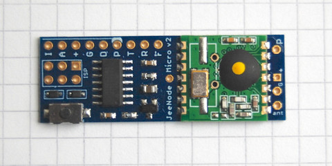 |
| Jeenode Micro |
This will be for later though.
For now I'm testing by means of a Jeelabs Jeelink, which is a simple RFM12B USB dongle running a simple firmware that allows sending and receiving packages via the wireless chip.
 |
| Jeelink |
High-level schematic
This picture gives a high-level overview of the whole setup.

To be continued
In further blog posts I will have a closer look at how it all fits together in practice, and have a look at the software aspect, and finally see the lamp fully working at is destined location. [ hopefully :) ]
Click here to go the the second part!
Click here to go the the second part!
Friday, March 29, 2013
madparts 1.0: first public release
I'm proud to present the first public release of madparts, the fully free software functional programmable electronics footprint editor.

Find all the details and downloads on the homepage at http://madparts.org/

Find all the details and downloads on the homepage at http://madparts.org/
Friday, March 1, 2013
using fragment shaders to draw shapes
Using openGL fragment shaders is an elegant way to draw shapes.
In this case it works by simply drawing a GL_QUAD (A simple unit square), but applying the shader on it to only selectively give certain coordinates in it color.
An openGL shader comes in two parts, a vertex shader and a fragment shader.
This is the vertex shader:
#version 120

// (c) 2013 Joost Yervante Damad
// License: GPL

// scale unit square to our rect size
// and move to it's origin

// input: (provided by calling program)
uniform vec2 size;  // size in x and y direction
uniform vec2 move;  // location

// output: (towards fragment shader)
varying vec2 pos2;    // adjusted position
varying vec2 size2;   // size in x and y direction

void main() {
  gl_FrontColor = gl_Color;
  vec4 vert = gl_Vertex;
  vert.x = vert.x * size.x;
  vert.y = vert.y * size.y;
  vec4 vert2 = vert;
  vert2.x += move.x;
  vert2.y += move.y;
  gl_Position = gl_ModelViewProjectionMatrix * vert2;
  pos2 = vec2(vert);
  size2 = size;
}
The role of the vertex shader is mainly to move to quad to the wanted coordinates and scale it to the size wanted. After that it is projected on our model.
And this is the fragment shader:
#version 120

// (c) 2013 Joost Yervante Damad
// License: GPL
// input provided by vertex shader
varying vec2 pos2;    // position
varying vec2 size2;   // size in x and y direction

void main() {
  // r: mininum size of straight side
  float q = sqrt(2.0)-1.0;
  float rx = size2.x * q;
  float ry = size2.y * q;
  float r = min(rx, ry);

  float shortest_size = min(size2.x, size2.y);
  float corner_size = (shortest_size - r) / 2;

  // a: minimum value where we want to cut off a corner
  float ax = (size2.x / 2) - corner_size;
  float ay = (size2.y / 2) - corner_size;

  // if we are in a corner zone:
  if (abs(pos2.x) > ax && abs(pos2.y) > ay) {
    // abs position within corner
    float x = abs(pos2.x) - ax;
    float y = abs(pos2.y) - ay;
    # are we inside the triangle ?
    if (x + y < corner_size) {
      gl_FragColor = gl_Color;
    }
  // else we're in a normal square zone:
  } else {
    glFragColor = gl_Color;
  }
}
The fragment shader is where it is decided for individual coordinates if they should be drawn or not.
The example here draws a nice rectangle with octagon style cut-off corners.
Wednesday, January 23, 2013
compiling and running coffeescript from within python
Running javascript from within python is already very easy using pyv8, the python wrapper for google's V8 javascript engine, like e.g. used within the Chrome browser.
On the other hand Coffeescript is a cool little language that compiles into javascript. I like it a lot more then javascript :)
I want to work with coffeescript from within python, without calling external tools.
The complication is that pyv8 provides a strict javascript environment. On the other hand coffeescript uses node.js and assumes all of it's libraries are available. (e.g. file I/O)
As the file I/O is not needed for my purpose, I just commented out the parts from the coffeescript code that use it.
The main missing part is the 'require' directive coffeescript uses from node.js, but which is not available when using plain V8 javascript. This can quite trivially be implemented in python.
However, this is still not enough, because of the way the functional wrapping is implemented in the javascript coffeescript generated for itself (coffeescript is written in coffeescript!) I had to change that generated code to explicitly return the "exports" object towards the caller of "require" because it would just return null by default. (+ a couple of other minor hacks here and there)
Here is all the python code:
 1 #!/usr/bin/env python
 2 #
 3 # (c) 2012 Joost Yervante Damad <joost@damad.be>
 4 #
 5 # License: CC0 http://creativecommons.org/publicdomain/zero/1.0/
 6
 7 import PyV8
 8 import os.path
 9
10 class Global(PyV8.JSClass):
11
12     def __init__(self):
13       self.path = ""
14
15     def require(self, arg):
16       content = ""
17       with open(self.path+arg+".js") as file:
18         file_content = file.read()
19       result = None
20       try:
21         store_path = self.path
22         self.path = self.path + os.path.dirname(arg) + "/"
23         result = PyV8.JSContext.current.eval(file_content)
24       finally:
25         self.path = store_path
26       return result
27
28 def make_js(coffee_script_code):
29   with PyV8.JSContext(Global()) as ctxt:
30     js_make_js_from_coffee = ctxt.eval("""
31 (function (coffee_code) {
32   CoffeeScript = require('coffee-script/coffee-script');
33   js_code = CoffeeScript.compile(coffee_code, null);
34   return js_code;
35 })
36 """)
37     return js_make_js_from_coffee(coffee_script_code)
38
39 coffee_script_code = """
40 yearsOld = max: 10, ida: 9, tim: 11
41
42 ages = for child, age of yearsOld
43   "#{child} is #{age}"
44 return ages
45 """
46
47 js_code = make_js(coffee_script_code)
48
49 print js_code
50
51 with PyV8.JSContext() as ctxt:
52   print PyV8.convert(ctxt.eval(js_code))
This is the output javascript from running the script:
 1 (function() {
 2   var age, ages, child, yearsOld;
 3
 4   yearsOld = {
 5     max: 10,
 6     ida: 9,
 7     tim: 11
 8   };
 9
10   ages = (function() {
11     var _results;
12     _results = [];
13     for (child in yearsOld) {
14       age = yearsOld[child];
15       _results.push("" + child + " is " + age);
16     }
17     return _results;
18   })();
19
20   return ages;
21
22 }).call(this);
23
And this is the result of the execution of the coffeescript:
['max is 10', 'ida is 9', 'tim is 11']
fun!
Monday, October 15, 2012
on demand and configurable Arduino HardwareSerial
At some point you want to tune a hardware serial interface. Typically to increase the receive buffer size because the sender sends fast and you need some time to do other stuff then just receive data.
Sometimes you don't use the serial interfaces at all, or only use it for sending short debug messages.
In all those cases you're potentially wasting quite a bit of RAM as Arduino always instantiates all available serial interfaces with the fixed buffer size of typically 64 bytes.
I thought it a fun little coding challenge to adapt the Arduino HardwareSerial code to use C++ template parameters. Those parameters can then be used to instantiate the HardwareSerial only when you need it and only with buffer sizes you want.
It turned out quite simple, and the following basic example Arduino sketch illustrates the principle:
In line 6 I instantiate the HardwareSerial instance. It has 3 template parameters:
Sometimes you don't use the serial interfaces at all, or only use it for sending short debug messages.
In all those cases you're potentially wasting quite a bit of RAM as Arduino always instantiates all available serial interfaces with the fixed buffer size of typically 64 bytes.
I thought it a fun little coding challenge to adapt the Arduino HardwareSerial code to use C++ template parameters. Those parameters can then be used to instantiate the HardwareSerial only when you need it and only with buffer sizes you want.
It turned out quite simple, and the following basic example Arduino sketch illustrates the principle:
 1 /* -*- Mode: C; tab-width: 2; indent-tabs-mode: nil -*- */
 2
 3 /* (c) 2012 Joost Yervante Damad <joost@damad.be> */
 4 /* License: GPL3+ */
 5
 6 static HardwareSerial<HARDWARE_SERIAL, 0, 16> MySerial;
 7
 8 void setup()
 9 {
10   MySerial.begin(31250);
11 }
12
13 static uint8_t c = 0;
14 void loop()
15 {
16   delay(50);
17   ++c;
18   MySerial.write((char)c);
19 }
In line 6 I instantiate the HardwareSerial instance. It has 3 template parameters:
- HARDWARE_SERIAL: this indicates we want the first hardware serial of the microcontroller. This is used to differentiate the underlying ports, etc at compile time. On an Arduino Mega you could also use HARDWARE_SERIAL1, HARDWARE_SERIAL2 or HARDWARE_SERIAL3.
- 0: This is the receive buffer size. In this case it is 0 meaning we don't want to receive anything and won't waste any bytes on a buffer. As an added bonus the interrupts for receiving will not be enabled.
- 16: This is the transmit buffer size. The test program is only sending single bytes, so we could even use 1 here!
I like how it turned but I fear it is a bit too complex to be part of the official Arduino tree.
The code can be found in github at:
Friday, October 12, 2012
software serial, a possible alternative implementation
(All code on this page is (c) 2012 Joost Yervante Damad and licenced under the GPL version 3)
Everybody at some point at least temporary needs more serial interfaces on their Arduino/ATMega/... micro-controller.
The usual solution is to use the software serial library. The existing implementations have some serious limitations so I'm working on an alternative solution.
First let's have a look at the existing ones and their features and limitations.
Before Arduino 1.0 there was a version which I will call "Old Software Serial".
Starting with Arduino 1.0 a library called "New Software Serial" was integrated.
This was written in 2006 by David A. Mellis.
Sending is done via setting the transmit pin HIGH and LOW and the timing of the bits is done by means of the "delayMicroseconds" call which does busy looping.
Receiving is done by calling the "read" function which will busy wait for the start of the byte and then read the bits where the timing between the bits is again done via delayMicroseconds.
It does not use any interrupts.
This works but has severe limitations:
In general there are a couple of special cases:
Everybody at some point at least temporary needs more serial interfaces on their Arduino/ATMega/... micro-controller.
The usual solution is to use the software serial library. The existing implementations have some serious limitations so I'm working on an alternative solution.
First let's have a look at the existing ones and their features and limitations.
Before Arduino 1.0 there was a version which I will call "Old Software Serial".
Starting with Arduino 1.0 a library called "New Software Serial" was integrated.
Old Software Serial
This was written in 2006 by David A. Mellis.
Sending is done via setting the transmit pin HIGH and LOW and the timing of the bits is done by means of the "delayMicroseconds" call which does busy looping.
Receiving is done by calling the "read" function which will busy wait for the start of the byte and then read the bits where the timing between the bits is again done via delayMicroseconds.
It does not use any interrupts.
This works but has severe limitations:
- sending data keeps the CPU busy
- receiving data also keeps the CPU busy
- if your program is not actively reading at the right time you will loose bytes
- only one instance can be active at once as reading is done in the main program
New Software Serial
This started it's life as AFSerial done by Lady Ada from Adafruit industries. It was then picked up by Mikal Hart from Arduiniana and there were bugfixes and improvements by various other people (Paul Stoffregen from the Teensy, ...) In Arduino 1.0 it was integrated as the "SoftwareSerial" library.
Sending works basically the same as in the Old Software Serial.
Receiving is interrupt based.
The receive pin is registered for pin change interrupts. This means every time the pin changes from LOW to HIGH or the other direction an interrupt is called.
In practice when a pin change happens and it is a HIGH->LOW transition this indicates a start bit and then the byte is read by means of short delays implemented via a busy loop. The byte is then inserted into a circular buffer. Reading from the main program just reads from that buffer.
The big improvement here is that reading does not require blocking the main program.
This works better then the Old Software Serial but also has limitations:
- sending data still keeps the CPU busy
- it only supports one active receiver; you have to change the active receiver with the listen() call if you have multiple instances of SoftwareSerial (this is actually a limitation caused by how reading a byte works)
- reading a byte BLOCKS busy looping within the interrupt handler
That last in particular is quite nasty. It means that while the library is reading a byte, no other interrupts can be handled. This Includes interrupts for a receive of another software serial instance or even another hardware serial interface! Normally the goal should be to have interrupt handlers do as little as possible.
JD Software Serial
Giving comments on other people's code is easy so let's put my money where my mouth is and try to come up with a better solution.
For now I'm focusing on the receive part, for the sending part I have some ideas about as well, but that is not that important as sending doesn't block interrupts and people expect it to be synchronous.
The basic idea is to also use the pin change interrupt, but instead of blocking to read an entire byte, look at the HIGH->LOW and LOW-HIGH transitions and the timing of when they happen and find out the bytes like that.
This approach also has some shortcomings and caveats, I'll get to that later.
A first try
First I'm going to write a simple interrupt handler that just puts the transitions in a 32bit circular buffer annotating each bit with it's timestamp. All this code is not optimized it is just to do some playing with the concept.
The type for the buffer and data fields for the interrupt:
 1 typedef uint32_t stamp_t;
 2 typedef struct {
 3   bool rise;
 4   stamp_t timestamp;
 5 } bitchange;
 6 static bitchange bitchanges[32] = { { 0,0 } };
 7 static int datapos = 31;
 8 static int freepos = 0;
 9 static volatile uint8_t * receivePortRegister = 0;
10 static uint8_t receiveBitMask = 0;
The interrupt handler:
 1 inline void handle_interrupt()
 2 {
 3   // if our bit change buffer is full, just drop this bit
 4   if (datapos == freepos) { return; }
 5   const uint8_t pin_data = *receivePortRegister & receiveBitMask;
 6   bitchanges[freepos].rise = pin_data > 0;
 7   bitchanges[freepos].timestamp = mytimer();
 8   freepos = (freepos + 1) & 31;
 9 }
10
11 ISR(PCINT0_vect)
12 {
13   handle_interrupt();
14 }
The mytimer() function uses the timer0 facility which is already in use by the Arduino core. It uses the lower 24 bit of the timer0 overflow counter together with the fast changing content of the TCNT0 register.
1 extern unsigned long timer0_overflow_count;
2 static inline stamp_t mytimer() {
3   const stamp_t ov = (timer0_overflow_count & 16777215l) << 8;
4   const uint8_t t = TCNT0;
5   return ov+t;
6 }
My setup uses two Arduino boards. Arduino one is sending a 'U' every second on it's TX pin, meaning it is using the hardware serial. It is clocked at 31250 baud.
That TX pin is connected to pin 2 on the second Arduino. The second arduino is connected with it's normal serial interface to a PC via USB at 115200 baud.
 |
| The setup. On the left the sender, on the right the receiver. Data is going via the green wire. |
To get started I just look at the bit transitions in a busy loop.
 1 void loop()
 2 {
 3   if ((datapos + 1)%32 != freepos) {
 4     const bool rise = bitchanges[datapos].rise;
 5     const stamp_t timestamp = bitchanges[datapos].timestamp;
 6     ATOMIC_BLOCK(ATOMIC_RESTORESTATE) {
 7       datapos = (datapos + 1) & 31;
 8     }
 9     Serial.print(timestamp); Serial.print(' ');   Serial.println(rise?'1':'0');
10 }
That works fine. Evert time it sees a byte it prints:
11835708 1
12085644 0
12085652 1
12085660 0
12085668 1
12085676 0
12085684 1
12085692 0
12085700 1
12085708 0
First line is the stop bit of the previous byte.
Second line is the start bit of this byte.
The remaining lines are the data bits.
The data bits give 10101010 which is LSB (Least significant bit) to MSB (most significant bit) meaning it represents 01010101 which is 0x55 which is 85 decimal which is the character 'U'. Now the reason I'm using that particular byte is that it has an edge on every bit, which makes it an easy case.
In general there are a couple of special cases:
- two or more times the same bit in one byte
- initially starting out in the middle of a byte
- ending with one or more HIGH bits meaning there is no stop bit interrupt
1 is easy to fix: just look at the time-stamps and insert extra bits with the previous bit value. The amount of bits can be determined from the difference of the current time-stamp and the previous time-stamp.
2 just implies that we need to be clever in trying to find the start bit in an existing stream.
3 is the tough one. The solution I'm implementing is that when a start bit is received and I was actually still expecting a data bit the remainder of the bits are filled with HIGH because that is what they might be.
However that does mean that the byte is only known when the next byte starts, which could be quite late. In practice though for the typical ASCII values this is not an issue as the MSB is 0, and the stop bit is always seen.
Get those bytes
Let's give decoding the bytes a stab. After quite some testing/tweaking I came with the following test code that nicely dumps the received byte and works for the whole 0 till 255 (0xFF) range:
 1 void loop()
 2 {
 3   if ((datapos + 1)%32 != freepos) {
 4     // first get data out of array
 5     const bool rise = bitchanges[datapos].rise;
 6     const stamp_t timestamp = bitchanges[datapos].timestamp;
 7     // only then update datapos to avoid getting overwritten data
 8     ATOMIC_BLOCK(ATOMIC_RESTORESTATE) {
 9       datapos = (datapos + 1) & 31;
10     }
11     // Serial.print(timestamp); Serial.print(' '); Serial.println(rise?'1':'0');
12     if (want_start) {
13       if (!rise) {
14         if (start_delay > 0) {
15           const stamp_t d = stampdiff(timestamp, prev_ts);
16           if (d < start_delay) {
17             // to soon, skip
18           } else {
19             want_start = false;
20             bit_count = 0;
21             recv_byte = 0;
22             start_delay = 0;
23             //Serial.print('T');
24           }
25         } else {
26           // \/ we actually receive what could be a start bit
27           want_start = false;
28           bit_count = 0;
29           recv_byte = 0;
30           //Serial.print('S');
31         }
32       } else {
33         //Serial.print('Q');
34         // /\ probably a stop bit; just discard and wait for next start
35       }
36     } else {
37       // we are receiving a byte
38       const stamp_t d = stampdiff(timestamp, prev_ts);
39       // Serial.println(d);
40       if (d > 80) {
41         // if it takes to long to get a bit, the byte has ended
42         if (!rise) {
43           // \/ we find what is possibly a new start bit
44           // this means we need to fill the remaining bits with
45           // /\ meaning a 1
46           const int num_bits_remaining = 8 - bit_count;
47           // Serial.print("+"); Serial.print(num_bits_remaining); Serial.print('-');
48           for (int i = 0; i  < num_bits_remaining; ++i) {
49             recv_byte >>= 1;
50             recv_byte += 128;
51           }
52           Serial.print('$');
53           Serial.println((int)recv_byte, HEX);
54           want_start = false;
55           bit_count = 0;
56           recv_byte = 0;
57         } else {
58           // /\ we're out of sync, restart
59           //Serial.println('*');
60           bit_count = 0;
61           want_start = true;
62           start_delay = 80;
63         }
64       } else {
65         // new edge within the same byte
66         // if the edge comes after double the expected time or more
67         // we've skipped a bunch of bit of the previous value
68         const int8_t prev_num_bits = ((d+1) / 8) - 1;
69         // Serial.print("+"); Serial.print(prev_num_bits); Serial.print('-');
70         // push previous bits
71         for (int8_t i = 0; i < prev_num_bits; ++i) {
72           recv_byte >>= 1;
73           recv_byte += rise ? 0 : 128; // inverse of what we're going to now
74           // Serial.print(rise ? 'O' : '|');
75           ++bit_count;
76         }
77         // push current bit
78         if (bit_count < 8) {
79           // Serial.print(rise ? '1' : '0');
80           recv_byte >>= 1;
81           recv_byte += rise ? 128 : 0;
82           ++bit_count;
83         }
84         if (bit_count >= 8) {
85           // we reached the end of the byte
86           Serial.print('#');
87           Serial.println((int)recv_byte, HEX);
88           want_start = true;
89         }
90       }
91     }
92     prev_ts = timestamp;
93   }
94 }
This actually somewhat works :)
Now comes the tough part to rework it to do the byte decoding in the interrupt handling and work with a circular buffer like New Software Serial. After that it needs to be optimized.
Also tables need to be made to accommodate different baud rates then the fixed 31250 baud used here.
An interesting thing is that because I'm already looking at time-stamps anyway, implementing auto-baud should not be hard!
Another future addition could be to actually sample the pin a second time shortly after the first time and if it's not the same discard the bit. This would work as a simple noise filtering.
To be continued in the near future!
Wednesday, April 6, 2011
debian, grub2, booting the "other OS"
Recently my debian installation switched to grub2 and the boot menu no longer showed a working entry for booting my old XP partition.
The solution is simple:
sudo apt-get install os-prober
sudo update-grub
From now on grub2 will automatically detect and add to its menu all other OS partitions on your local disks.
The solution is simple:
sudo apt-get install os-prober
sudo update-grub
From now on grub2 will automatically detect and add to its menu all other OS partitions on your local disks.
Sunday, August 22, 2010
digicorder and recording subsequent programs
Digital television is getting the norm in Belgium, and typically people rent a "digicorder" from the TV provider. This allows you to watch television and also record programs for later consumption.
In practice my family only records a few programs and watch them later. It's very convenient not to be bound to a specific schedule. (On the other hand it would probably be cheaper to just buy the DVD boxes of the series we like instead of having television at all, but that is another discussion :) ).
In general, the digicorder works fine, I have one big gripe with it though: recording of subsequent programs.
Lets say we're recording subsequent programs A and B from channel 0. Let's assume there is some advertisement in between programs. This gives as timescale something like this:

Now, there are three ways the digicorder can record the program, not counting the completely faulty ways when timing goes all wrong.
Both programs want to record a time-slice before and after their program, but this goes wrong in the middle, and only one recording ends up with the middle part.
The correct recording is with the break point in the middle like this:

I presume there are not some kind of markers in between the broad-casted programs on commercial television because it makes their advertisement store even worse.
Therefor, in practice you typically end up with one if these two:

This is problematic because if you don't remember not to erase recording 1 after watching program A, the start of program 2 will be lost.

This is even worse. Lets say you want to watch program B first.
You first have to open recording 1, fast forward all the way to the start of program B, start watching and after a few minutes switch to recording 2. This will also leave recording 1 marked as "watched" even though you didn't watch program A yet. More confusion!
In the end this is a simple technical problem with an even simpler solution: record the overlap in a separate file and make it part of both recordings. Visual:

If you watch recording 1, you get recording 1 + X. If you watch recording 2, you get X + recording 2.
If you erase recording 1, X stays. Only if both recording 1 and recording 2 are erased, X gets deleted.
More in general there will be X areas both in front and at the end, etc...
Would be nice if the biggest TV provider of Belgium could implement this. If the digicorder was open source I would've done this already months ago...
I guess I'll have to look into some kind of MythTV like setup one day.
In practice my family only records a few programs and watch them later. It's very convenient not to be bound to a specific schedule. (On the other hand it would probably be cheaper to just buy the DVD boxes of the series we like instead of having television at all, but that is another discussion :) ).
In general, the digicorder works fine, I have one big gripe with it though: recording of subsequent programs.
Lets say we're recording subsequent programs A and B from channel 0. Let's assume there is some advertisement in between programs. This gives as timescale something like this:
Now, there are three ways the digicorder can record the program, not counting the completely faulty ways when timing goes all wrong.
Both programs want to record a time-slice before and after their program, but this goes wrong in the middle, and only one recording ends up with the middle part.
correct
The correct recording is with the break point in the middle like this:
I presume there are not some kind of markers in between the broad-casted programs on commercial television because it makes their advertisement store even worse.
Therefor, in practice you typically end up with one if these two:
B in recording 1
This is problematic because if you don't remember not to erase recording 1 after watching program A, the start of program 2 will be lost.
A in recording 2
This is even worse. Lets say you want to watch program B first.
You first have to open recording 1, fast forward all the way to the start of program B, start watching and after a few minutes switch to recording 2. This will also leave recording 1 marked as "watched" even though you didn't watch program A yet. More confusion!
A simple solution
In the end this is a simple technical problem with an even simpler solution: record the overlap in a separate file and make it part of both recordings. Visual:
If you watch recording 1, you get recording 1 + X. If you watch recording 2, you get X + recording 2.
If you erase recording 1, X stays. Only if both recording 1 and recording 2 are erased, X gets deleted.
More in general there will be X areas both in front and at the end, etc...
Would be nice if the biggest TV provider of Belgium could implement this. If the digicorder was open source I would've done this already months ago...
I guess I'll have to look into some kind of MythTV like setup one day.
Saturday, July 17, 2010
arduino-0018, avrdude and usbtiny programmer
For some reason the avrdude binary that is shipped with arduino-0018 has no support for the USBtiny programmer which I use to burn bootloaders on blank AVR atmega328 microcontrollers.
On Debian the workaround is simple: first install avrdude via apt-get/aptidude and then enter the hardware/tools directory in the arduino-0018 dir and replace avrdude by a softlink to /usr/bin/avrdude like this:
After this burning a bootloader via the menu in arduino works fine again. A similar approach will probably work on other Linux distributions.
On Debian the workaround is simple: first install avrdude via apt-get/aptidude and then enter the hardware/tools directory in the arduino-0018 dir and replace avrdude by a softlink to /usr/bin/avrdude like this:
$ cd arduino-0018/hardware/tools
$ mv avrdude avrdude.old1
$ ln -s /usr/bin/avrdude .
$ mv avrdude.conf avrdude.conf.old1
$ cp /etc/avrdude.conf .
After this burning a bootloader via the menu in arduino works fine again. A similar approach will probably work on other Linux distributions.
Friday, February 12, 2010
Nokia N82 Bluetooth + GPRS/3G
A few months ago I did an interesting discovery about using my cellphone to go on the internet via bluetooth. I had this strange situation before where it just stopped working, and after revisiting all configs it worked again.
What really happens is that my cellphone somehow crashes, after which I power cycle it by removing the batteries. The phone then boots again, but here is the twist: the service channels in the phone are re-allocated and apparently in a random order!
This implies that the RFCOMM channel configured in the /etc/bluetooth/rfcomm.conf file is possible wrong now!
Solution: just browse the services again with sdptool browse, adapt the file and it should work again!
Saturday, May 30, 2009
how to set a serial port at MIDI speed in linux
Linux serial ports only work at standard speeds by default. MIDI runs at 31250 baud, which is not a standard speed. However there are tricks to get custom speeds, but documentation is quite fuzzy. This is a simple recipe that worked for me with an FT232 USB-Serial board.
Check the baud base of the device:
$ setserial -g -a /dev/ttyUSB0
/dev/ttyUSB0, Line 0, UART: unknown, Port: 0x0000, IRQ: 0
Baud_base: 24000000, close_delay: 0, divisor: 0
closing_wait: infinite
Flags: spd_normal low_latency
As you can see the baud base is 24000000 here.
Next calculate the divisor by dividing the baud_base you see here by the speed you want.
In my case 24000000/31250=768.
Apply the new setting:
$ setserial -v /dev/ttyUSB0 spd_cust divisor 768
Next start your serial application, you might want to make sure it is already set to the correct speed before you do the above changes else it might destroy your settings. The correct speed is 38400 baud, which is now aliased to 31250.
With minicom just use the menu (CTRL-A Z) to change the settings.
Screen can be used like this:
screen /dev/ttyUSB0 38400
Exit screen by pressing CTRL-A CTRL-\
Sweet.
Tuesday, April 28, 2009
arduino toolkit on x86_64 linux Debian/Ubuntu
Update:
I received an email from Ethan Bisset with a much nicer solution: just use the debian provided serial library instead of the one provided with the arduino software.
(below is the old entry:)
Download the linux 32-bit arduino toolkit from the arduino toolkit download page and untar in a directory.
Install the avr tools: apt-get install avr-libc binutils-avr gcc-avr
Install "ia32-sun-java5-bin". ( apt-get install ia32-sun-java5-bin )
Adapt the "arduino" startup script script and replace java in it by
/usr/lib/jvm/ia32-java-1.5.0-sun/bin/java
Execute the "arduino" startup script. It works just fine now.
Thats all.
Many thanks to the Debian java packagers for providing this 32-bit compatibity jvm!
I received an email from Ethan Bisset with a much nicer solution: just use the debian provided serial library instead of the one provided with the arduino software.
This is his recipe:
1. Get arduino software
2. apt-get install sun-java6-bin binutils-avr avr-libc gcc-avr librxtx-java
3. Untar arduino software
4. Delete <arduino>/lib/librxtxSerial.so
5. Done!
(below is the old entry:)
Download the linux 32-bit arduino toolkit from the arduino toolkit download page and untar in a directory.
Install the avr tools: apt-get install avr-libc binutils-avr gcc-avr
Install "ia32-sun-java5-bin". ( apt-get install ia32-sun-java5-bin )
Adapt the "arduino" startup script script and replace java in it by
/usr/lib/jvm/ia32-java-1.5.0-sun/bin/java
Execute the "arduino" startup script. It works just fine now.
Thats all.
Many thanks to the Debian java packagers for providing this 32-bit compatibity jvm!
Subscribe to:
Posts (Atom)