This picture shows the lamp with the new LED already in place, hanging from a ladder, to give an impression of the size.

I decided to make it a lamp with the following specifications:
- using a modern, very high power LED for serious brightness and yet good efficiency
- fully dimmable
- optional automatic dimming with ambient light sensing
- temperature sensing and overheat protection
- passive cooling or else using a low speed inaudible fan
- remote controllable
Besides that I wanted to use mostly readily available breakout boards to minimize time spent researching sensors and writing drivers.
LED
After some research I decided to use the CREE XLamp CXA2530 which is a very modern LED with a very high brightness and great efficiency. I chose a warm-white color temperature variant.

It has some very impressive specs:
- Size: 23.85mm x 23.85mm
- Maximum drive current: 1.5A
- Maximum power: 61W
- Light output: 3000 – 5700lm
- Typical forward voltage @ 0.8 A, 85°C: 37V
- Viewing angle: 115 degrees
- Thermal resistance: 0.8 °C/W
For more details and full specifications visit the CREE website. To give you a rough idea: at 30W this LED gives light equivalent to a more then 100W incandescent lamp.
Power supply
As the LED used needs some serious power a very good power supply will be needed. It should be able to provide up to 40V at 1A, be constant current based, and would ideally support dimming out of the box.
After some research I settled on the MeanWell HLM-40H-42B which is really quite expensive but has very high efficiency, can provide the requirement voltage and current, and has dimming built-in.
Dimming works by means of a PWM signal that is provided to the module. This signal will be provided by the micro-controller. The module also supports dimming via a sense resistor.
When no dimming signal is provided the power supply is fully on. This implies that in case the PWM signal from the micro-controller disappears, the LED will be fully on. By shorting the dim connector with a 10k resistor the lamp will fall-back to a ~10% dimmed state when the micro-controller fails to provide the dimming signal. The PWM signal is strong enough to take prescedence when active.
Micro-controller
As micro-controller breakout board I'm using a JeeNode v6.

This is an Arduino compatible micro-controller board based on an Atmel atmega328p like in Arduino UNO. It comes with an on-board HopeRF RFM12B 868Mhz RF interface. The provided JeeLib software is installed as a library and provides access to 4 "ports" on the board in a convenient way.
Each port supports what is called a "plug" in the Jee-world.
I'm using two plugs and the other two ports are used directly for their pins.
Lux sensing
Lux sensing is done by means of the JeeLabs LuxPlug. This is based on a simple I2C bus lux measurement IC.

The result is a 16-bit light intensity number that can be used for automatic dimming of the lamp.
Temperature sensing
The temperature is measured near the LED die by means of a K-type thermocouple. The thermocouple signal is amplified by an AD597 IC provided by the JeeLabs Thermo Plug.

The temperature can be used by the micro-controller to shutdown the lamp in case over overheating or to control the fan speed depending on the temperature.
Fan control
Some initial testing showed that the temperature of the LED rises really fast, even with a large heat-sink attached. Some more testing showed that doing active cooling with a large fan running at a low (inaudible) speed makes a large (>10°C) difference, and a cooler LED is a happier LED with a longer lifetime.
I settled on installing a 12cm PC fan. With the sides cut of it is a perfect fit inside if the top of the lamp, sucking out air upwards.

In order to allow cables to enter the lamp from above without blocking the fan, a simple spacer is needed. The 3D-printer to the rescue! This picture also shows part of the heat-sink at the top. The heat-sink is not really ideal and I plan to use other heat-sinks for future builds.
Finally the fan is mounted and running nicely. This picture also shows the LED mounted on the case with some pieces of aluminium, some screws and some thermal paste. If you look carefully you also see the tip of the thermocouple sitting under the aluminium very near to the LED.

The fan also provides a pulse per rotation signal on another wire. This signal is connected on the pin for the INT1 interrupt facility of the micro-controller. In the interrupt handler a counter is incremented for each activation. By them sampling this counter every second I get a rough value on the rotations/second speed of the fan. If the speed drops below a certain threshold the lamp can be turned of for safety reasons.
Relay
While just fully dimming turns the lamp off, this still means that the LED power supply is powered and in case of some failure the lamp might turn on again.
To be able to fully turn of the driver a relay is inserted on the AC line before the power supply. The specific relay I'm using is a dual-pole, dual coil, latching relay.
Dual-pole means that it can switch both wires of the AC, completely disconnecting the power supply when off.
Dual coil latching means that the relay has a separate coil for turning on and for turning off. To change state one of the coils is activated for a short time only. This means the relay uses no power when active, only when changing state.
Here is the relay wired up to be integrated in the lamp setup.

An added complexity is that the relay coils operate at 5V and the micro-controller only provides 3.3V (and limited current) on the digital outputs.
As the micro-controller gets 5V in this is easily remedied by introducing two low-side N-channel switching mosfets.
The next simple (untested!) schematic shows how this could be done.

[Update: the circuit above is flawed in that the IRF540 mosfets require at least 4V and I'm providing a 3V3 signal. I replaced them by BC935 NPN BJT transistors, and removed R3 and R4]
Remote control
In order to be able to control the lamp remotely I want to make a simple remote based on the Jeelabs Jeenode Micro, and more specific the variant with the build-in boost converter that can be easily run from only one 1.5V battery.
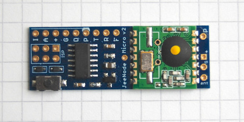 |
| Jeenode Micro |
This will be for later though.
For now I'm testing by means of a Jeelabs Jeelink, which is a simple RFM12B USB dongle running a simple firmware that allows sending and receiving packages via the wireless chip.
 |
| Jeelink |
High-level schematic
This picture gives a high-level overview of the whole setup.

To be continued
In further blog posts I will have a closer look at how it all fits together in practice, and have a look at the software aspect, and finally see the lamp fully working at is destined location. [ hopefully :) ]
Click here to go the the second part!
Click here to go the the second part!
No comments:
Post a Comment