This is part 3 and for now the final part of this series of posts on my experiment with using a mosfet for dimming a 12V LED strip as the strip is going to be used for lighting up my soldering desk (undimmed).
In part two I found that using a 100nF snubber capacitor filters out the Drain-Source ringing. However I noticed a large drop in Drain voltage from the expected 12V when the mosfet is disabled. As last time, K made an interesting comment, this time that the circuit seems seriously overdamped.
Let's try and actually use the formulas K mentions in the comments and which can be found in the article Calculating Optimal Snubbers.
The datasheet for the IRF540 mosfet shows a Drain-Source capacitance of 375pF (C) at 12V.
Assuming a ringing time (T) of 200ns and using the formula T=2*pi*sqrt(L*C) gives a parasitic inductance of 2.2uH.
This gives a snubber resistance R=sqrt(L/C) ~= 100Ω. With C=T/R this gives a snubber capacitance of 2.2nF.
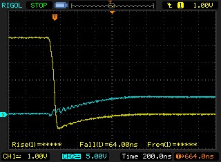
100Ω 2.2nF snubber
The snubber does give a damping effect, but still a nasty initial peak of 30V.
Remeasuring the period shows actually more in the direction of 400ns. Recalculating like above gives 10uH parasitic inductance. The snubber gives 190Ω and 1nF.
190Ω 1nF snubber
Note that I changed the vertical scale of the blue line to 10V. This means we have a nasty spike of 36V, which is definitely worse.
As this still doesn't look very well I started playing with values.
47Ω 1nF
0Ω 4.7nF snubber (blue 10V scale)
0Ω 4.7nF snubber (blue 5V scale)
0Ω 3.3nF snubber
0Ω 10nF snubber
As you can see increasing the capacitance reduces the peak, but also reduces the end voltage below the expected 12V.
I finally settled for the 0Ω 3.3nF snubber. It gives some minimal ringing but stays near 12V. As it requires no resistor there is no resistive loss.
Measuring the power usage shows no significant difference between the snubbed and plain circuit. I still think that some parts of the story have not been revealed here. Maybe in a future blog post...
In a previous post I looked at PWM dimming a 12V LED strip. Time to revisit this with some new insights. So I saw bad ringing at turn-off of the mosfet. According to K the noise is caused by the capacitance of the Drain-Source of the power mosfet in combination with the inductance of the load. This makes sense as I already figured out that changing the load influenced the ringing.
Let's do a proper "snubber". (Not "shunt" as I called it last time).
I'm re-measuring with the gate voltage on the yellow channel and the drain voltage on the blue channel of the scope. Notice that the blue channel has a 5V per division scale and the yellow one 1V per division.
no snubber
Without snubber that looks absolutely horrible.
Second lets add a 100nF capacitor from drain to VCC like I did in the previous post.
"snubber" cap to VCC
That is with a "snubber" cap to VCC, which arguably is not really a snubber at all.
Finally, lets really add the snubber over the Drain and Source of the mosfet, which means Drain to ground as the Source is directly connected to ground.
snubber cap across drain-source
That looks nice!
There is still some high frequency noise (~20Mhz) but it has a very low amplitude.
Let's go back to the initial situation, is it really a problem? I guess with the mosfet I'm using (IRF540), not really. It has a Drain Source breakdown voltage of 100V, and the largest peak I notice is 40V. On the other hand that might just go past the breakdown voltage of the LEDs on the LED strip and that is not a good thing either.
A curious thing is that in the non-snubbed circuit the drain voltage goes all the way up to almost 12V and in the snubbed circuit it only goes up to 5V. It looks like the LED strip in combination with the snubber acts as some kind of impedance divider.
If I change the snubber from 100nF to 1uF (10x larger) the peak voltage on the Drain drops to 4V. Changing it to 50nF raises the peak voltage to 6V.
Sugru is air-curable silicone rubber. It is easily shape-able by hand and cures in about a day. It stays good for about 6 months in the original packages, but I store it in the fridge where it will stay good a bit longer.
Etching tank
When I'm not etching I want to store the etchant away in a safe place. I use glass jars stored in a hazardous materials container for that. The tricky thing is to pour the etchant from the tank into the glass jars without spoiling any as it is both toxic and corrosive. The tank being rectangular in shape makes this nearly impossible.
The solution: a sugru-made (I mixed two colors here) round shaped high side-walled pouring guide.
A test run with water show it works great. Not a single drop of spill.
Screw protector
This is actually something fixed by Isabelle. One of the screw protectors in the horse trailer got missing and she was worried her horse might injure herself on the exposed screw. Some sugru to the rescue!
On the right the normal screw protector, on the left the sugru fix.
Fridge
One of the knobs to keep a panel in place in the fridge had broken off. We probably overloaded that particular part in the panel, although it is also arguably a week construction. It is fixed with sugru and seems to hold until now, although we also re-organized the fridge to get a better weight distribution. Sorry for the unclear picture but I didn't feel like taking the fridge apart again.
Conclusion
Sugru is handy stuff! Highly recommended to have some off it in your house, especially as it allows you to easily fix things you might normally just throw away and buy anew. Less waste is good!
Dimming a 12V LED strip with an N-channel power mosfet is pretty straightforward. In this experiment I'm using 5 meter of cool white LED strip running at about 800 mA giving 10 Watt.
the basic setup
An Arduino Duemilanove (my trusty lucky white one) is used to provide pulse with modulation ( PWM ). Digital pin 9 and 10 (also known as OC1A and OC1B) are used. They both use the Timer2 facility of the atmega328p microcontroller which means I can have them output exactly the same PWM signal. Digital 9 is used to drive the mosfet and digital 10 is only used for displaying the unloaded PWM signal on the scope.
Basic PWM setup schematic
PWM on the scope
On the scope you can see the yellow PWM signal driving the mosfet and the blue one that is not connected to any load.
The following Arduino sketch does a simple PWM sweep in 10 steps per second:
This gives a PWM signal as shown in the (crude) video below.
Not shown in the video is that this also nicely dims the LED strip.
This is actually good enough for simple dimming, but lets look at it more in detail. More specific lets look at the rise and fall of the PWM signal at the gate of the mosfet.
a detailed look at the voltage at the rising edge at the gate of the mosfet
Whats interesting to see is that it takes about 600ns in total to go from 0V to 5V at the mosfet gate.
The first sharp rise is from 0V across the threshold voltage of the mosfet to the Miller plateau voltage and takes about 100ns. At this point the current through the mosfet is already at the peak but the voltage across the mosfet from drain to source still has to drop from the 12V it starts at. This drop happens across the relatively flat part of the peak in the middle called the Miller plateau region. After this drop the Drain-Source voltage for this particular mosfet will be a bit above 150mV and the remaining 11.85V will be across the LED strip. Finally the voltage at the gate rises to 5V which will slightly lower the on-resistance of the mosfet and the final Drain-Source voltage should be about 100mV.
As mentioned all this takes about 600ns which is not very fast. Looking at the specification of the IRF540 mosfet a rise time of about 35ns should be possible.
The basic idea to get a faster transition is driving more current in the mosfet gate then the measly 50mA that the digital pin of the Arduino/atmega is capable of providing.
One solution suggested by the paper is to use a Bipolar totem-pole driver. The idea behind that is that by using the very fast operation and large gain of bipolar transistors the gate can be charged and discharged quickly.
adding the bipolar totem-pole mosfet driver
When the PWM signal is high the NPN transistor is on and the PNP transistor is off. This allows a large current to flow from the 5V power supply and the tank capacitor C into the mosfet gate.
PWM high and NPN on
When the PWM signal is low the PNP transistor is on and the NPN transistor is off allowing for a quick sink of the charge on the mosfet gate into ground.
PWM low and PNP on
For the transistors a BC639 NPN and a BC640 PNP do the job. R is 3.3Ω. RB is 22Ω. RGATE is 4.7Ω. C is a big 1000μF electrolytic.
final setup
improved rise time
A rise time of 44ns using the bipolar totem-pole driver is not bad at all.
Lets take a look at the other side of the wave form.
fall ringing
There is some nasty ringing on the fall side of the pulse. This won't affect the dimming but it's interesting anyway to take a look what is happening.
First thing I checked is RGATE. Increasing the resistance off RGATE does lower the ringing but it also kills the just gained speed improvement.
Then I noticed something weird: if I unrolled part of the LED strip the peaks of the ringing got larger. I then replaced the LED strip by a single LED and surely the ringing is all but gone.
I assume the capacitance/inductance of the 5 meter LED strip and/or all its LEDs cause the ringing.
Adding a shunt resistor across the LED strip lowers the amplitude of the ringing but it requires quite a low ohm resistor which in turn gets very hot when there is 12V across it, and it wastes a bit of energy.
Measurement with the scope shows that the ringing is at about 3.5Mhz. A simple shunt capacitor of 100nF should nicely act as a low-pass filter. If we presume a parasitic resistance of 1Ω, using f = 1/(2*pi*R*C) gives about 1.5Mhz cut-off frequency for the filter.
schematic with CSHUNT added
with 100nF filter
That certainly looks nice. I still don't think it is more then aesthetics though..
I'd love to hear comments on this! Either here or on G+.