Let's look how easy it is to implement a simple cookie based language switch in the rocket web framework for the rust programming language.
Defining the language type:
In this case there will be support for Dutch and English. PartialEq is derived to be able to compare Lang items with ==.
The Default trait is implemented to define the default language:
The FromStr trait is implemented to allow creating a Lang item from a string.
The Into<&'static str> trait is added to allow the conversion in the other direction.
Finally the FromRequest trait is implemented to allow extracting the "lang" cookie from the request.
It always succeeds and falls back to the default when no cookie or an unknown language is is found.
How to use the Lang constraint on a request:
And the language switch page:
And as a cherry on the pie, let's have the language switch page automatically redirect to the referrer. First let's implement a FromRequest trait for our own Referer type:
When it finds a Referer header it uses the content, else the request is forwarded to the next handler. This means that if the request has no Referer header it is not handled, and a 404 will be returned.
Finally let's update the language switch request handler:
Pretty elegant.
A recap with all code combined and adding the missing glue:
Showing posts with label programming. Show all posts
Showing posts with label programming. Show all posts
Saturday, June 17, 2017
Monday, January 20, 2014
programming the attiny10 in linux
The attiny10 (and it's brothers attiny4,5 and 9) is a cute little 6-pin SOT23-6 AVR micro-controller. The very tiny footprint and low price makes it interesting as replacement for e.g. the 555 in simple circuits.
Programming it seems to have been quite involved but the more recent gcc supports it just fine, making it finally easier to use. I tested with 4.8.1 downloaded from Atmel, as the one provided by Debian (also 4.8.1) did not yet have the definitions for the attiny10. It seems like the public source tree for the avr tool lags behind quite a bit against the Atmel provided toolchain ...
For programming I'm using an AVRISP-MKII. I updated it to the latest firmware. This updating unfortunately requires avrstudio in windows; programming itself works fine in Linux.. You may also need a recent avrdude. I'm using 6.0.1.
Programming requires that the chip is powered by 5V according to the spec. I can confirm that this is the case because I tried it with 3.3V and it didn't work, it tries to program but fails on verification.
Once programmed the chip runs all the way down to 1.8V.
The pin mapping is pretty obvious:
attiny10 pinout:

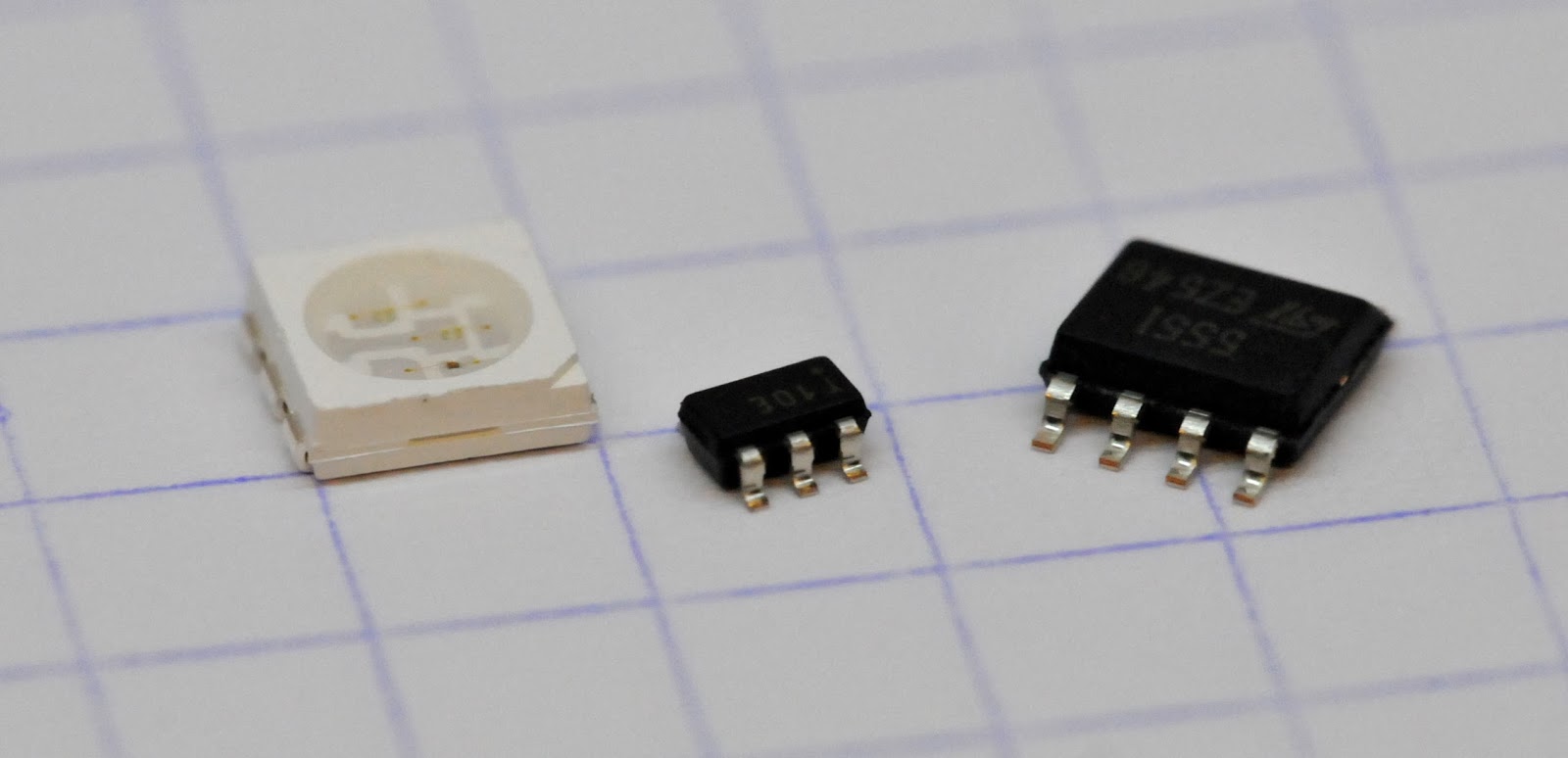 |
| attiny10 sitting between a 5050 RGB LED and a 555 timer IC |
Programming it seems to have been quite involved but the more recent gcc supports it just fine, making it finally easier to use. I tested with 4.8.1 downloaded from Atmel, as the one provided by Debian (also 4.8.1) did not yet have the definitions for the attiny10. It seems like the public source tree for the avr tool lags behind quite a bit against the Atmel provided toolchain ...
For programming I'm using an AVRISP-MKII. I updated it to the latest firmware. This updating unfortunately requires avrstudio in windows; programming itself works fine in Linux.. You may also need a recent avrdude. I'm using 6.0.1.
Programming requires that the chip is powered by 5V according to the spec. I can confirm that this is the case because I tried it with 3.3V and it didn't work, it tries to program but fails on verification.
Once programmed the chip runs all the way down to 1.8V.
The pin mapping is pretty obvious:
attiny10 pinout:
- PB0/TPIDATA
- GND
- PB1/TPICLK
- PB2
- VCC
- PB3/RESET
AVRISP-MkII pinout:
- MISO
- VCC
- SCK
- MOSI
- RESET
- GND
And the mapping:
- TPIDATA - MISO
- TPISCK - SCK
- RESET - RESET
- GND - GND
- VCC - VCC
The following C++ code blinks a LED every second on pin PB2:
#include <util/delay.h>
#include <avr/io.h>

static inline void setup() {
  // configure PB2 pin
  PUEB &= ~_BV(PUEB2);   // disable Pull-Up
  DDRB |= _BV(DDB2);     // enable Output mode
  PORTB &= ~_BV(PORTB2); // set output to Low
}

int main() {

  setup();

  while (true) {

    PORTB &= ~_BV(PORTB2);
    _delay_ms(500);

    PORTB |= _BV(PORTB2);
    _delay_ms(500);
  }

  return 0;
}
The following makefile builds it and uploads it with the help of avrdude:
# Makefile loosely derived from generated avr toolchain makefile

PROG   := avrispmkii
MCU    := attiny10
F_CPU  := 1000000
TARGET := blink

COMMONFLAGS = -g -Os -funsigned-char -funsigned-bitfields \
  -fpack-struct -fshort-enums -Wall -DF_CPU=$(F_CPU) -mmcu=$(MCU)

CFLAGS = -std=gnu99 $(COMMONFLAGS) -Wstrict-prototypes \
  -Wa,-adhlns=$(<:.c=.lst) \

CXXFLAGS = -std=gnu++11 $(COMMONFLAGS) -fno-exceptions -fno-rtti \
  -Wa,-adhlns=$(<:.cc=.lst) \

ASFLAGS = -Wa,-adhlns=$(<:.S=.lst),-gstabs
LDFLAGS = -Wl,-Map=$(TARGET).map,--cref

# TODO fuses
# FUSE:=-U lfuse:w:0xff:m -U hfuse:w:0xd9:m -U efuse:w:0xff:m

AVRDUDE:=avrdude -c $(PROG) -p $(MCU)
AVRDUDE_WRITE_FLASH = -U flash:w:$(TARGET).hex

TC = /your/path/to/avr8-gnu-toolchain-linux_x86_64

CC      = $(TC)/bin/avr-gcc
CXX     = $(TC)/bin/avr-c++
OBJCOPY = $(TC)/bin/avr-objcopy
OBJDUMP = $(TC)/bin/avr-objdump
SIZE    = $(TC)/bin/avr-size

default: $(TARGET).hex

check:
 $(AVRDUDE)

fuse:
 $(AVRDUDE) $(FUSE)

upload:
 $(AVRDUDE) $(AVRDUDE_WRITE_FLASH)

%.hex: %.elf
 $(OBJCOPY) -O ihex -R .eeprom $< $@
 $(SIZE) $@

.SECONDARY : $(TARGET).elf
.PRECIOUS : $(OBJ)
%.elf: %.o
 $(CC) $(CFLAGS) $< --output $@ $(LDFLAGS)

%.o : %.c
 $(CC) -c $(CFLAGS) $< -o $@

%.o : %.cc
 $(CXX) -c $(CXXFLAGS) $< -o $@

%.s : %.c
 $(CC) -S $(CFLAGS) $< -o $@

%.o : %.S
 $(CC) -c $(ALL_ASFLAGS) $< -o $@

clean:
 -rm *.hex
 -rm *.lst
 -rm *.obj
 -rm *.elf
 -rm *.o
In action:
Tuesday, December 24, 2013
using madparts for making electronics footprints: an eleborate example
In this blog post I'm discussing a more complex footprint I've made and how I made it with madparts based on the vendor's specification. More specifically I'm making a footprint for the Bluegiga BLE113 Bluetooth Low Energy module.
Lets start by collecting all the needed data.


Define the size of the pad as found in the recommended landing pattern:
The horizontal pads need an adjustment from the center of the module. The landing pattern defines 5.35mm between the two columns of pads, and we orient from the center of the pad so in total this gives and adjustment value of:
The landing pattern tells us the distance between pads:
The pinout description gives the number of pins:
The physical dimension tells us the distance from the bottom of the module to the center of the bottom left and right pad. This works because the pad centers are the same for the physical diagram and the landing pattern.
Now this gets a bit tricky. We need to calculate the vertical adjustment needed for the column of pads, but this is relative to the center of the module. The trick is to take pad 18, move it to the 0 point, then to the bottom of the module, and then use the lr_pad_to_bottom adjust value specified in the spec.
Let's draw a rectangle to document the module shape, and draw a silk around it to make it easily visible on the board later.
Let's define the pad shape with the earlier defined constant. we want 100% round corners.
Now lets make the left row of pads. First make them, then adjust the x and y by the values we calculated earlier.
Next the bottom row. clone and rotate the pad, and create a horizontal row of pads. Adjust the y as specified in the landing pattern figure. Finally renumber starting with the number after the last number we used for the first column of pads.
Finally the right row. Again a single row of pads. Reverse the order. Renumber starting after the last number used for the down pads.
Let's add a name somewhere inside the module, a bit below the top:
Let's add a rectangular for the restrict area. This is a but messy but it boils down to placing it right above pas 36 and 3.5mm on the right of the left side of the module.
Finally combine it all in a list and we're done.
The latest version of the full file can be found at https://github.com/andete/madparts-parts/blob/master/3ca17b8bc41648d2b968c33ae8f35092.coffee
This is a screenshot:

And this is the part in eagle cad:

And in kicad:

Lets start by collecting all the needed data.
The physical dimensions of the module are found in the spec page 16:
This will be used to define the physical boundaries of the package.
Next is the landing pattern. It can be found on page 17 of the specification:
This is used to define the pads for the module.
The order of the pins can be found on page 7:

Finally the specification also gives a clearance for the antenna on page 20:
This means we'll have to add a restrict area to the part for this clearance area.
let's write code!
Define the size of the module as found in the physical dimensions:
  module_dx = 9.15
  module_dy = 15.74
Define the size of the pad as found in the recommended landing pattern:
  pad_dx = 2
  pad_dy = 0.5
The horizontal pads need an adjustment from the center of the module. The landing pattern defines 5.35mm between the two columns of pads, and we orient from the center of the pad so in total this gives and adjustment value of:
pad_hadj = (5.35+pad_dx)/2
The landing pattern tells us the distance between pads:
pad_between = 0.8
The pinout description gives the number of pins:
  n_left = 18
  n_down = 6
  n_right = 12
The physical dimension tells us the distance from the bottom of the module to the center of the bottom left and right pad. This works because the pad centers are the same for the physical diagram and the landing pattern.
lr_pad_from_bottom = 1.45
Now this gets a bit tricky. We need to calculate the vertical adjustment needed for the column of pads, but this is relative to the center of the module. The trick is to take pad 18, move it to the 0 point, then to the bottom of the module, and then use the lr_pad_to_bottom adjust value specified in the spec.
  pad_vadj = ((n_left-1)/2)*pad_between  # move pad 18 to 0
  pad_vadj -= module_dy/2                # move pad 18 down to bottom
  pad_vadj += lr_pad_from_bottom         # and back up by 1.45
Let's draw a rectangle to document the module shape, and draw a silk around it to make it easily visible on the board later.
  r1 = make_rect module_dx, module_dy, 0.1, 'docu'
  r2 = make_rect module_dx+0.2, module_dy+0.2, 0.1, 'silk'
Let's define the pad shape with the earlier defined constant. we want 100% round corners.
  pad = new Smd
  pad.dx = pad_dx
  pad.dy = pad_dy
  pad.ro = 100
Now lets make the left row of pads. First make them, then adjust the x and y by the values we calculated earlier.
  l1 = single pad, n_left, pad_between
  l1 = adjust_x l1, -pad_hadj
  l1 = adjust_y l1 , pad_vadj
Next the bottom row. clone and rotate the pad, and create a horizontal row of pads. Adjust the y as specified in the landing pattern figure. Finally renumber starting with the number after the last number we used for the first column of pads.
  l2 = rot_single (rotate90pad clone pad), n_down, pad_between
  l2 = adjust_y l2, -module_dy/2+lr_pad_from_bottom-0.55
  l2 = generate_names l2, n_left
Finally the right row. Again a single row of pads. Reverse the order. Renumber starting after the last number used for the down pads.
  l3 = single pad, n_right, pad_between
  l3 = reverse l3
  l3 = generate_names l3, n_left+n_down
  l3 = adjust_x l3, pad_hadj
  l3 = adjust_y l3, pad_vadj+(n_right-n_left)/2*pad_between
Let's add a name somewhere inside the module, a bit below the top:
name = new Name (module_dy/2-1)
Let's add a rectangular for the restrict area. This is a but messy but it boils down to placing it right above pas 36 and 3.5mm on the right of the left side of the module.
  k = new Rect
  k.type = 'restrict'
  k.dx = module_dx
  k.dy = module_dy/2-l3[n_right-1].y
  k.x = -module_dx/2+3.5+k.dx/2
  k.y = l3[n_right-1].y+pad_dy/2+k.dy/2
Finally combine it all in a list and we're done.
combine [name, r1,r2, l1, l2,l3, k]
The latest version of the full file can be found at https://github.com/andete/madparts-parts/blob/master/3ca17b8bc41648d2b968c33ae8f35092.coffee
This is a screenshot:

And this is the part in eagle cad:

And in kicad:

Sunday, December 15, 2013
madparts release 1.2.1
This is mostly a bug-fix release, mainly fixing bugs to do with rotation of certain parts, especially in combination with KiCAD export.
Builds are available for Debian Jessie and Wheezy, Ubuntu Saucy, MacOSX and Win32.
Go download one of them at http://madparts.org/footprint.html#download !

Builds are available for Debian Jessie and Wheezy, Ubuntu Saucy, MacOSX and Win32.
Go download one of them at http://madparts.org/footprint.html#download !

Saturday, December 14, 2013
stm32f105 cortex-m3 getting to blink
This is not going to be a detailed post. All the code can be found in github at https://github.com/andete/blog-stuff/tree/master/STM32F105 .
In my quest for more experience with different microcontrollers I made a little breakout for the ST STM32F105 ARM Cortex-M3 micro-controller.
The breakout provides a 8Mhz external clock, which is multiplied by 9 by the internal PLL to give a nice 72Mhz clock.

The MCU is programmed with the STLINK V2 programmer via SWD. It should also be possible to program it via DFU but I have not tried that yet.
I cobbled some code together from all over the internet to make a simple blink file.
#include "stm32f10x.h"

// loosely based on
// http://www.overtracks.com/stm32/baby-steps.htm
// http://dics.voicecontrol.ro/dicsEE-IP/chapter/Setting%20GPIO%20manually
// http://infocenter.arm.com/help/index.jsp?topic=/com.arm.doc.dui0497a/BGBEEJHC.html
// https://forum.sparkfun.com/viewtopic.php?f=11&t=21107
// http://en.radzio.dxp.pl/stm32vldiscovery/

// LED is connected to PC0, so first bit on GPIOC
#define LED_BITMASK          1 << 0 // bit 0

#define USE_SYSTICK

#ifdef USE_SYSTICK
void SysTick_Handler(void) {
  GPIOC->ODR ^= LED_BITMASK; // toggle LED state
}
#else
void TIM3_IRQHandler(void) {
  // why the check for UIF ?
  if (TIM3->SR & TIM_SR_UIF) // if UIF flag is set
  {
    TIM3->SR &= ~TIM_SR_UIF; // clear UIF flag
    GPIOC->ODR ^= LED_BITMASK; // toggle LED state
  }
}
#endif

int main() {

  // enable GPIOC
  RCC->APB2ENR |= RCC_APB2ENR_IOPCEN;
  // configure GPIOC port 0 as output; 4 bits per pin
  // 4+0 -> (0) input mode, (4) floating (reset state)
  // 0+2 -> (2) output mode, (0) generic push-pull
  GPIOC->CRL = 0x44444442;

#ifdef USE_SYSTICK
  // 1 second = 72000000 / 8000000 = 9000000
  SysTick->LOAD = 9000000;
  // start counting from zero
  SysTick->VAL = 0;
  // enable and enable interrupt
  SysTick->CTRL |= (SysTick_CTRL_ENABLE_Msk | SysTick_CTRL_TICKINT_Msk);
#else
  // enable clock for timer3
  RCC->APB1ENR |= RCC_APB1ENR_TIM3EN;
  // Set prescaler to 24 000 (PSC + 1) // why?
  TIM3->PSC = 23999;
  // // Auto reload value 1000
  TIM3->ARR = 1000;
  // Enable update interrupt (timer level)
  TIM3->DIER = TIM_DIER_UIE; // Enable update interrupt (timer level)
  TIM3->CR1 = TIM_CR1_CEN;   // Enable timer

  NVIC_EnableIRQ(TIM3_IRQn);
#endif

  // sleep till the end of time
  while (1) { __WFI(); }
  return 0;
}
It does blinking via the SysTick interrupt or alternatively via the TIM3 timer interrupt.
It is also possible to do this without interrupts at all, just using the timers, but this is not shown here.
Monday, August 19, 2013
madparts release 1.2
It's been a few months, but finally the new madparts 1.2 release is available!
Madparts is a functional electronics footprint editor with support for the Kicad and Eagle electronics Cad programs.
Madparts is a functional electronics footprint editor with support for the Kicad and Eagle electronics Cad programs.
 |
| screenshot of madparts 1.2 running on linux/xmonad |
Highlights
KiCad support
Finally full support for importing and exporting footprints from/to KiCad is now available. madparts supports both the old .mod file format and the newer .pretty/.kicad_mod file format.
More shapes
1.2 adds support for arcs, partial circles, polygons and holes.
QtScriptEngine
Alex Schultz contributed javascript handling with QtScriptEngine instead of PyV8. This means there is one less dependency for the program making it easier to install, package and maintain. It is also faster! Thanks again Alex!
More documentation
Documentation is still sparse, but there is some more description of the supported features and code structures. Be sure to also have a look at my own private github repo of madparts footprints for more code examples.
Conclusion
If you want to give it a try, head to the website at http://madparts.org/ for more information and downloads. If you find issues or have questions, don't hesitate to email me.
The future
For madparts 1.3 a few changes are planned:
- switch to SVG based graphics rendering to get rid of the dependency on modern openGL 2.1, making the program also usable on older computers
- more documentation
- better error handling
Saturday, August 10, 2013
using the atxmega32e5 under linux
The Atmel AVR atxmega*e5 is an interesting chip. However it is still rather new so getting it to work on my linux environment took some tinkering.

Compiling requires a compiler that knows the CPU. In the previous post I just cheated and used a mostly compatible CPU.
Besides the compiler, avr-libc also needs to be adapted. It is avr-libc that provides the io description headers for the CPU's. There is no avr-libc for linux yet that does this. Luckily Atmel's AVR Studio product also uses gcc internally, and they already support the atxmega*e5 CPU's.
Besides that, some other files are needed. I took the files crtx8e5.o, crtx16e5.o and crtx32e5.o from avr studio and copied these to /usr/lib/avr/lib/avrxmega2/
With those two in place, compilation works :)
Here is an example that demonstrates the following:

compiler
Compiling requires a compiler that knows the CPU. In the previous post I just cheated and used a mostly compatible CPU.
My Debian comes default with gcc 4.7.3 which does not support the new atxmega*e5 CPU's yet. Luckily someone already packaged the gcc 4.8.1 compiler source, so it was just a matter of recompiling Debian's gcc-avr package against the gcc 4.8.1 source package. If you don't feel like that using the atxmega*D4 as cpu type during compilation is doable.
avr-libc
Besides the compiler, avr-libc also needs to be adapted. It is avr-libc that provides the io description headers for the CPU's. There is no avr-libc for linux yet that does this. Luckily Atmel's AVR Studio product also uses gcc internally, and they already support the atxmega*e5 CPU's.
I took the files iox8e5.h, iox16e5.h and iox32e5.h from avr studio and copied these to /usr/lib/avr/include/avr/ .
Also /usr/lib/avr/include/avr/io.h needs to be updated to add the new CPU's:
--- io.h.old 2013-08-10 09:51:40.963241968 +0200
+++ io.h 2013-08-10 13:29:12.682545107 +0200
@@ -382,12 +382,6 @@
 #  include <avr/iox32a4.h>
 #elif defined (__AVR_ATxmega32D4__)
 #  include <avr/iox32d4.h>
+#elif defined (__AVR_ATxmega8E5__)
+#  include <avr/iox8e5.h>
+#elif defined (__AVR_ATxmega16E5__)
+#  include <avr/iox16e5.h>
+#elif defined (__AVR_ATxmega32E5__)
+#  include <pavr/iox32e5.h>
 #elif defined (__AVR_ATxmega64A1__)
 #  include <avr/iox64a1.h>
 #elif defined (__AVR_ATxmega64A1U__)
With those two in place, compilation works :)
Example
- switch to the internal 32Mhz oscillator
- configure an USART on ports D6 and D7 at 9600 baud and run a simple echo follower
- blink a LED on port A0
// (c) 2013 Joost Yervante Damad <joost@damad.be>
// License: GPL3
#include <avr/io.h>
#include <util/delay.h>
#include <avr/interrupt.h>

static void usart_write(uint8_t data)
{
    USARTD0.DATA = data;
    if(!(USARTD0.STATUS & USART_DREIF_bm)) {
        while(!(USARTD0.STATUS & USART_TXCIF_bm)); // wait for TX complete
    }
    USARTD0.STATUS |= USART_TXCIF_bm;  // clear TX interrupt flag
}


static inline void init_oscillator() {
  // enable 32Mhz internal oscillator
  OSC.CTRL |= OSC_RC32MEN_bm;
  // wait for it to be stable
  while (!(OSC.STATUS & OSC_RC32MRDY_bm));
  // tell the processor we want to change a protected register
  CCP=CCP_IOREG_gc;
  // and start using the 32Mhz oscillator
  CLK.CTRL=CLK_SCLKSEL_RC32M_gc;
  // disable the default 2Mhz oscillator
  OSC.CTRL&=(~OSC_RC2MEN_bm);
  // enable 32kHz calibrated internal oscillator
  OSC.CTRL|= OSC_RC32KEN_bm;
  while (!(OSC.STATUS & OSC_RC32KRDY_bm));
  // set bit to 0 to indicate we use the internal 32kHz
  // callibrated oscillator as auto-calibration source
  // for our 32Mhz oscillator
  OSC.DFLLCTRL = OSC_RC32MCREF_RC32K_gc;
  // enable auto-calibration for the 32Mhz oscillator
  DFLLRC32M.CTRL |= DFLL_ENABLE_bm;
}

static inline void init_usart() {
  // enable clock out on port PC7
  PORTCFG.CLKOUT = (PORTCFG.CLKOUT & ~PORTCFG_CLKOUTSEL_gm) | PORTCFG_CLKOUT_PC7_gc;
  // set PC7 as output
  PORTC.DIRSET = PIN7_bm;

  // set PD7 as output for TX0
  PORTD.DIRSET = PIN7_bm;
  PORTD.OUTSET = PIN7_bm;
  // remap USARTD0 to PD[7-4]
  PORTD.REMAP |= PORT_USART0_bm;
  // set baud rate 9600: BSEL=12, BSCALE=4
  // as found in table in
  // Atmel-42005-8-and-16-bit-AVR-Microcontrollers-XMEGA-E_Manual.pdf
  USARTD0.BAUDCTRLA = 12; // BSEL
  USARTD0.BAUDCTRLB = 4 << USART_BSCALE_gp; // BSCALE
  // disable 2X
  USARTD0.CTRLB = USARTD0.CTRLB & ~USART_CLK2X_bm;
  // enable RX and TX
  USARTD0.CTRLB = USARTD0.CTRLB | USART_RXEN_bm | USART_TXEN_bm;
  // enable async UART 8N1
  USARTD0.CTRLC = USART_CMODE_ASYNCHRONOUS_gc | USART_PMODE_DISABLED_gc | USART_CHSIZE_8BIT_gc;
  USARTD0.CTRLC &= ~USART_SBMODE_bm;
  USARTD0.CTRLD = 0; // No LUT

  // set interrupt level for RX
  USARTD0.CTRLA = (USARTD0.CTRLA & ~USART_RXCINTLVL_gm) | USART_RXCINTLVL_LO_gc;
}

static inline void init_interrupts() {
  // Enable PMIC interrupt level low
  PMIC.CTRL |= PMIC_LOLVLEX_bm;
  // enable interrupts
  sei();
}

static volatile uint8_t echo_char = 42;

int main( void )
{
  init_oscillator();

  // enable clock out on port PC7
  PORTCFG.CLKOUT = (PORTCFG.CLKOUT & ~PORTCFG_CLKOUTSEL_gm) | PORTCFG_CLKOUT_PC7_gc;
  // set PC7 as output
  PORTC.DIRSET = PIN7_bm;

  init_usart();

  init_interrupts();

  // set PA0 as output
  PORTA.DIRSET = PIN0_bm;
  // blink LED on PA0 with 1 second on, 1 second off
  // write echo_char on USART on D7; defaults to 42(*)
  while (1) {
    usart_write(echo_char);
    PORTA.OUTSET = PIN0_bm;
    _delay_ms( 1000 );
    usart_write(echo_char);
    PORTA.OUTCLR = PIN0_bm;
    _delay_ms( 1000 );
  }
}

// USART RX receive interrupt handler
ISR(USARTD0_RXC_vect) {
  echo_char = USARTD0.DATA;
}
Code
I have some extra atxmega32e5 breakout boards available. You can find them in my tindie store.
 |
| breakout on a breadboard with USB-serial adapter |
In addition, the eagle schematic and board files are available on github as well.
More fun
I'm still exploring this nice little microcontroller. Be sure to check back later on my blog for new adventures!
Wednesday, August 7, 2013
atxmega enable internal 32Mhz oscillator (part 2)
The atxmega also supports using the calibrated internal 32kHz clock as auto-calibration reference for the 32Mhz internal oscillator, improving the accuracy.
This code should do the trick. I'm not sure how I could actually verify it. Perhaps I can get the clock signal external and get it on a scope.
This code should do the trick. I'm not sure how I could actually verify it. Perhaps I can get the clock signal external and get it on a scope.
#include <avr/io.h>
#include <util/delay.h>

int main( void )
{
  // enable 32Mhz internal oscillator
  OSC.CTRL|=OSC_RC32MEN_bm;
  // wait for it to be stable
  while (!(OSC.STATUS & OSC_RC32MRDY_bm));
  // tell the processor we want to change a protected register
  CCP=CCP_IOREG_gc;
  // and start using the 32Mhz oscillator
  CLK.CTRL=CLK_SCLKSEL_RC32M_gc;
  // disable the default 2Mhz oscillator
  OSC.CTRL&=(~OSC_RC2MEN_bm);
  // enable 32kHz calibrated internal oscillator
  OSC.CTRL|= OSC_RC32KEN_bm;
  while (!(OSC.STATUS & OSC_RC32KRDY_bm));
  // set bit to 0 to indicate we use the internal 32kHz
  // callibrated oscillator as auto-calibration source
  // for our 32Mhz oscillator
  OSC.DFLLCTRL &= ~OSC_RC32MCREF_bm;
  // enable auto-calibration for the 32Mhz oscillator
  DFLLRC32M.CTRL |= DFLL_ENABLE_bm;

  // set PA0 as output
  PORTA.DIRSET = 0b00000001;

  // blink LED on PA0 with 1 second on, 1 second off
  while (1) {
    PORTA.OUTSET = 0b00000001 ;
    _delay_ms( 1000 );
    PORTA.OUTCLR = 0b00000001 ;
    _delay_ms( 1000 );
  }
}
Tuesday, August 6, 2013
atxmega enable 32Mhz internal oscillator
The atxmega (I'm playing with an atxmega16e5) has multiple internal oscillators. By default it starts on the 2Mhz clock, which is actually an 8Mhz internal oscillator divided by 4. The following code switches to the 32Mhz internal oscillator.
register definitions can be found in iox16e5.h. As I'm using an older avr-gcc I've looked in iox16d4.h instead, assuming that the base registers like for the clock are the same.
register definitions can be found in iox16e5.h. As I'm using an older avr-gcc I've looked in iox16d4.h instead, assuming that the base registers like for the clock are the same.
#include <avr io.h>
#include <util delay.h>

int main( void )
{
  // enable 32Mhz internal oscillator
  OSC.CTRL|=OSC_RC32MEN_bm;
  // wait for the oscillator to stabilize
  while (!(OSC.STATUS & OSC_RC32MRDY_bm));
  // tell the processor we want to change a protected register
  CCP=CCP_IOREG_gc;
  // and start using the 32Mhz oscillator
  CLK.CTRL=CLK_SCLKSEL_RC32M_gc;
  // finally disable the default 2Mhz oscillator (optional)
  OSC.CTRL&=(~OSC_RC2MEN_bm);

  // set PA0 as output
  PORTA.DIRSET = 0b00000001;

  // blink LED on PA0 with 1 second on, 1 second off
  while (1) {
    PORTA.OUTSET = 0b00000001 ;
    _delay_ms( 1000 )
    PORTA.OUTCLR = 0b00000001 ;
    _delay_ms( 1000 )
  }
}
Tuesday, July 30, 2013
adding a new device to avrdude
So I made a little breakout for the new Atmel AtXmega E5 series. More specifically I'm testing it with the atxmega16e5.
This is a new chip that is not yet supported by the latest avrdude.
Making it work turned out to be reasonably straightforward.
First let's open avrdude.conf, the config file of avrdude.
Let's find a section of a chip that is reasonably similar, I've selected the atxmega16d4:
copy this to a new section and change the id to x16e5 and the desc to ATxmega16E5.
This seems to work fine for programming. I'm pretty sure some things are still missing concerning fuses and such though.
In order to get code compiled with gcc I use another atxmega target as chip as the x16e5 is not yet part of
the avr-gcc I'm using either.
./avrdude -C ./avrdude.conf -e -P usb -c avrispmkII -p x16e5 -U flash:w:blink.hex
And it blinks :)
This is a new chip that is not yet supported by the latest avrdude.
Making it work turned out to be reasonably straightforward.
First let's open avrdude.conf, the config file of avrdude.
Let's find a section of a chip that is reasonably similar, I've selected the atxmega16d4:
#------------------------------------------------------------
# ATxmega16D4
#------------------------------------------------------------

part parent ".xmegasmall"
    id  = "x16d4";
    desc = "ATxmega16D4";
    signature = 0x1e 0x94 0x42;
    has_jtag = no;

    memory "eeprom"
        size  = 0x0400;
        offset  = 0x08c0000;
        page_size = 0x20;
        readsize = 0x100;
    ;

    memory "application"
        size  = 0x00004000;
        offset  = 0x0800000;
        page_size = 0x100;
        readsize = 0x100;
    ;

    memory "apptable"
        size  = 0x00001000;
        offset  = 0x00803000;
        page_size = 0x100;
        readsize = 0x100;
    ;

    memory "boot"
        size  = 0x00001000;
        offset  = 0x00804000;
        page_size = 0x100;
        readsize = 0x100;
    ;

    memory "flash"
        size  = 0x00005000;
        offset  = 0x0800000;
        page_size = 0x100;
        readsize = 0x100;
    ;
;
copy this to a new section and change the id to x16e5 and the desc to ATxmega16E5.
Find the signature like by hooking up the PDI to your x16e5 board and doing:
avrdude -P usb -c avrispmkII -p x16d4
It will now say that it is the wrong signature and will print you the signature it actually found:
0x1e 0x94 0x45
Use that in the config section.
Now find the XML files distributed as part of Atmel AVR Studio that contain the device descriptions of the two devices: ATxmega16D4.xml and ATxmega16E5.xml
Now look at the differences and make the necc. changes. The only changes I made are the eeprom size, the page_size and readsize settings. The x16e5 uses 128 byte pages and the x16d4 256 byte pages.
This gives as a result:
#------------------------------------------------------------
# ATxmega16E5
#------------------------------------------------------------

part parent ".xmegasmall"
    id  = "x16e5";
    desc = "ATxmega16E5";
    signature = 0x1e 0x94 0x45;
    has_jtag = no;

    memory "eeprom"
        size  = 0x0200; # J
        offset  = 0x08c0000;
        page_size = 0x20;
        readsize = 0x80; # J was 0x100
    ;

    memory "application"
        size  = 0x00004000;
        offset  = 0x0800000;
        page_size = 0x80;
        readsize = 0x80;
    ;

    memory "apptable"
        size  = 0x00001000;
        offset  = 0x00803000;
        page_size = 0x80;
        readsize = 0x80;
    ;

    memory "boot"
        size  = 0x00001000;
        offset  = 0x00804000;
        page_size = 0x80;
        readsize = 0x80;
    ;

    memory "flash"
        size  = 0x00005000;
        offset  = 0x0800000;
        page_size = 0x80;
        readsize = 0x80;
    ;
;
This seems to work fine for programming. I'm pretty sure some things are still missing concerning fuses and such though.
In order to get code compiled with gcc I use another atxmega target as chip as the x16e5 is not yet part of
the avr-gcc I'm using either.
./avrdude -C ./avrdude.conf -e -P usb -c avrispmkII -p x16e5 -U flash:w:blink.hex
And it blinks :)
Tuesday, July 23, 2013
high power LED retrofit (part 5)
So it's been a while since I showed progress on my LED retrofit project. I've been mostly busy preparing the madparts 1.2 release, which should happen "real soon now".
I'm hoping to switch to KiCAD soon, but these boards were still designed with Eagle CAD.

Let's look at the different sections in detail:

12V is taken in with a standard power connector. Diode D3 is used to protect against reverse polarity. F1 is a re-settable polyfuse, which combined with the TVS diode D4 provides further overloading protection.

The 12V rail is converted to a 5V and 3.3V rail by means of MCP1703 voltage regulators.

Headers are provided for Debug TX/RX serial interface, I2C bus for the Lux sensor and the standard 6-pin ISP programming header.
The I2C bus is actually connected to 5V, but the Lux sensor I'm using runs on 3.3V only. (It dies on 5V :( ) This means I had to do some bodge wiring to get 3.3V instead of 5V on that connector.
The Lux sensor is only connected to one of the two boards I've created because they'll be together anyway.

The main workhorse is an Atnel AVR atmega328p microcontroller clocked at 16Mhz. A conservative choice but it allowed me to spent minimal time making the firmware as it is fully Arduino compatible. I also broke out the other pins just to be sure but I did not end up using those.
 The wireless connection is provided by a cheap RFM12B module. It is connected to the SPI bus of the main processor. This module runs on 3.3V hence the simple voltage divider action for MOSI, SCK and SS signals that go from the processor to the RFM12B. The other way around nothing is needed as 3.3V is still above the high-threshold for the processor.

The relay used is a neat little latching relay to avoid constantly powering the relay when the lamp is on. The relay is driven from the micro-controller via the NPN transistors T1 and T2 and flyback protection diodes D1 and D2 are provided around the relay coils to absorb possible inductive kicks.

Finally an adjustable voltage regulator together with a trim pot is used to set the peak voltage of the PWM signal towards the LED driver. This can be used to limit the maximum current provided by the LED driver. This works because internally the LED driver just converts the PWM signal to a voltage anyway with a low-pass filter. This adds another safety mechanism to limit the LED current if your setup is not capable of dissipating all the heat the LED die produces when it is running at it's maximum current rating.
The PWM signal provided by the micro-controller is then first inverted an then brought up to almost the voltage level provided by the voltage regulator. In practice a small drop is still seen causing a 10V maximum output signal when the voltage regulator is set to 10.5V.
R12 ensures that the LED drops to 10% dimming instead of going full on if for some reason the board dies and the lamp is still on as the LED driver also supports programming the current with a resistor.
Finally this gives rise to the following board layout:

The code has also been rewritten. I will not further explain the code.
You can find code and eagle schematic and board files at https://github.com/andete/blog-stuff/tree/master/HPLEDRF2/relay_pwm .
Note that I mirrored the power connector. Luckily I could just cut off the side pin and it still works fine.

Many parts are the same as the other board and I will not go in them again. These are different:
The fan PWM is just directly driven from the micro-controller as the FAN has 5V PWM compatible. The fan also provides a pulse signal which is connected to the INT1 interrupt pin of hte micro-controller.

Temperature sensing is provided by the AD8495 k-type thermocouple amplifier. I did not write my own driver for it, I just used code already made available by http://adafruit.com/ .
This is the board layout:

For this board, the code and files can be found at https://github.com/andete/blog-stuff/tree/master/HPLEDRF2/temp_fan .


PCBs
As discussed in the previous post, while I had everything working for one lamp, it was a total mess of cables and really not acceptable to be a permanent part of the home. Also I wanted to decouple the functionality in two parts:
- LED PWM, relay control and Lux sensing
- fan PWM and temperature measurement
Main reason being that fan PWM and temperature measurement need to be done relatively close to the actual lamp, while the others should be done close to the LED driver.
To avoid having to run cables between the two boards, and because I'm using RF already anyway, I decided to let both boards talk directly over wireless.
Schematics & board design
I'm hoping to switch to KiCAD soon, but these boards were still designed with Eagle CAD.
LED PWM, relay control and Lux sensing
Overal schematic:
Let's look at the different sections in detail:

12V is taken in with a standard power connector. Diode D3 is used to protect against reverse polarity. F1 is a re-settable polyfuse, which combined with the TVS diode D4 provides further overloading protection.


Headers are provided for Debug TX/RX serial interface, I2C bus for the Lux sensor and the standard 6-pin ISP programming header.
The I2C bus is actually connected to 5V, but the Lux sensor I'm using runs on 3.3V only. (It dies on 5V :( ) This means I had to do some bodge wiring to get 3.3V instead of 5V on that connector.
The Lux sensor is only connected to one of the two boards I've created because they'll be together anyway.

The main workhorse is an Atnel AVR atmega328p microcontroller clocked at 16Mhz. A conservative choice but it allowed me to spent minimal time making the firmware as it is fully Arduino compatible. I also broke out the other pins just to be sure but I did not end up using those.


The relay used is a neat little latching relay to avoid constantly powering the relay when the lamp is on. The relay is driven from the micro-controller via the NPN transistors T1 and T2 and flyback protection diodes D1 and D2 are provided around the relay coils to absorb possible inductive kicks.

Finally an adjustable voltage regulator together with a trim pot is used to set the peak voltage of the PWM signal towards the LED driver. This can be used to limit the maximum current provided by the LED driver. This works because internally the LED driver just converts the PWM signal to a voltage anyway with a low-pass filter. This adds another safety mechanism to limit the LED current if your setup is not capable of dissipating all the heat the LED die produces when it is running at it's maximum current rating.
The PWM signal provided by the micro-controller is then first inverted an then brought up to almost the voltage level provided by the voltage regulator. In practice a small drop is still seen causing a 10V maximum output signal when the voltage regulator is set to 10.5V.
R12 ensures that the LED drops to 10% dimming instead of going full on if for some reason the board dies and the lamp is still on as the LED driver also supports programming the current with a resistor.
Finally this gives rise to the following board layout:

The code has also been rewritten. I will not further explain the code.
You can find code and eagle schematic and board files at https://github.com/andete/blog-stuff/tree/master/HPLEDRF2/relay_pwm .
Note that I mirrored the power connector. Luckily I could just cut off the side pin and it still works fine.
Fan PWM and temperature sensing
Overal schematic:

The fan PWM is just directly driven from the micro-controller as the FAN has 5V PWM compatible. The fan also provides a pulse signal which is connected to the INT1 interrupt pin of hte micro-controller.

Temperature sensing is provided by the AD8495 k-type thermocouple amplifier. I did not write my own driver for it, I just used code already made available by http://adafruit.com/ .
This is the board layout:

For this board, the code and files can be found at https://github.com/andete/blog-stuff/tree/master/HPLEDRF2/temp_fan .
Boards
I ordered boards from http://seeedstudio.com. They took slightly longer then 2 weeks to arrive counting from first order date which is very reasonable given that they have to come from China. Pricing is also extremely competitive.

.
The boards look reasonably well. The silk screen is a bit poor at places. I did not find any electrical errors (besides my own :p ). Copper does tends to peel of when you do rework, so don't use to much heat.
In the meanwhile I have also other boards in progress from http://oshpark.com/. I'm quite curious how long they'll take to get in Europe and make a comparison of the quality.
Assembly

Here is a picture of a fan-temperature board hand assembled. It went pretty well.

Here I'm testing temperature measurement with a k-type thermocouple.


Here you can see the relay PWM board sitting on top of the LED driver for testing. the Lux sensor is mounted on the lid of the case sensing through a hole.

Here I'm testing the entire setup with LED driver and LED PWM board below and temperature-fan board sitting on top of the stairs.
It's all starting to work!


As I want two of these lamps in my living, I started on assembly of the second lamp. I've slight changed the mounting. in the first lamp I used screws and aluminium to put the LED die in place. Here I've used termo-conductive glue to place the die on the plate. This has a big advantage that there are no screws in the way and the heat sink sits snugly on the other side of the plate. Also I've opted to mount the fan directly on the heat sink for simplicity.
On the top picture you can nicely see the thermocouple mounted on the LED die. Insulated with kapton tape.

With both lamps working fine, it's time to clean up the assembly for their final wiring. Wiring is always such a mess...

Here is the final wiring for the LED PWM boards and the LED drivers. Wires will of course be flattened when they're at their final location, and the cases will be closed. At this point I finished up the firmware as once the lamps are in place it will be next to impossible to reach the boards.
So all that is left is mounting them on a piece of wood and hanging the lamps on their final spot!
Friday, May 31, 2013
BufferSerial: let Arduino Stream writes go in a buffer
When you have existing code that uses an Arduino Stream like "Serial" or "SoftwareSerial" data is written part by part on the serial device. Sometimes you want to collect different parts first, maybe adding something like a checksum and only then send everything on one go. By using the BufferSerial construct you can just keep the existing code, pass it the BufferSerial instead of your normal Serial and afterward use the content of the buffer, and send it as one big blob.
A simple example:
The code for BufferSerial is really simple and can be found at: https://github.com/andete/blog-stuff/tree/master/BUFSER1 .
A simple example:
uint8_t mybuffer[32];
BufferSerial bs(mybuffer, 32);
bs.print((int)42);
bs.write(' ');
bs.print(127, HEX);
bs.print("hello");

Serial.println(bs);
The code for BufferSerial is really simple and can be found at: https://github.com/andete/blog-stuff/tree/master/BUFSER1 .
Friday, May 24, 2013
madparts release 1.1
A new release of the madparts functional electronics footprint editor is available.
Important changes are:
Important changes are:
- py2exe simple Windows installation: just unzip the zip file and execute madparts.exe
- linux packages for madparts and pyv8 for Debian and Ubuntu i386 and x86_64
- a ton of bug-fixes
- various internal code cleanups
- simple built-in command line interface for listing of libraries and import and export of footprints
For downloads, and more details head over to the madparts.org website. As always, don't hesitate to contact me with questions or feedback at joost@madparts.org or use the github bugtracker.
The next release will normally contain support for KiCad, but I first I need to learn working with it :)
 |
| madparts running on macosx |
Thursday, May 2, 2013
high power LED retrofit (part2)
In this second part we're looking at the code that is going to control the LED lamp. Remark that the code discussed is the code as it is today (2/5/2013), for the latest code, go to github.
Also note that this is the code without the auto-dimming as that feature is still under test.
Also note that this is the code without the auto-dimming as that feature is still under test.
Ports & Plugs
static PortI2C bus1(1);
static LuxPlug lux_plug(bus1, 0x39);
static Port fan_port(2);
static Port temperature_port(3);
static Port relay_port(4);
Here the Jeenode ports are set up. We're using all 4 ports. Port 1 is connected to a software I2C bus, which is used by the lux_plug. Port 2 is a simple port, which we use for fan control. Port 3 is another simple port which we use for temperature control and port 4 is finally used to switch the relay.
global state
static uint8_t counter = 0;
#define DATA_MSG_SIZE 11
static uint8_t data_msg[DATA_MSG_SIZE];
Some global state. A counter which is inserted in responses to have an increasing number for testing, and a message buffer which is used for building up the response to the message that queries the system state.
LED PWM
namespace led_pwm {
  static const byte PIN = 9;
  static byte setting = 35;

  static inline void setup() {
    pinMode(PIN, OUTPUT);
    analogWrite(PIN, setting);
  }

  static inline void set_dim(const uint8_t dim) {
    setting = dim;
    analogWrite(PIN, setting);
  }
}
Pretty straightforward, using Arduino pin 9 for PWM, this is not a pin that is part of one of the Jeenode ports, but is instead available on a separate header.
fan
namespace fan {
  static const uint8_t default_pwm_setting = 35;
  static uint8_t pwm_setting = 0;
  volatile uint16_t pulse_count = 0;
  static uint16_t pulse_count_save = 0;
  static uint8_t pulse_per_second = 10;

  void pulse_interrupt() {
    ++pulse_count;
  }

  static inline void normal() {
    pwm_setting = default_pwm_setting;
    fan_port.anaWrite(pwm_setting);
  }

  static inline void setup() {
    fan_port.mode(OUTPUT);
    attachInterrupt(1, pulse_interrupt, FALLING);
    normal();
  }
  static inline void update_pulse_per_second() {
    const uint16_t l = pulse_count;
    pulse_per_second = l - pulse_count_save;
    pulse_count_save = l;
  }

  static inline void full_blast() {
    pwm_setting = 255;
    fan_port.anaWrite(pwm_setting);
  }

  static inline void off() {
    pwm_setting = 0;
    fan_port.anaWrite(pwm_setting);
  }
}
PWM handing is quite similar to the LED PWM, except here the fan_port Jeenode port is used to access the digital pin. In the setup method an interrupt handler is registered for the INT1 interrupt calling pulse_interrupt() on the falling edge. This causes pulse_count to be incremented for each pulse received from the fan. update_pulse_per_second() is then called every second to calculate a new pulse_per_second by simply looking at the difference.
temperature
namespace temperature {
  static int8_t value = 0;

  static inline void beep(const int16_t len = 100) {
    temperature_port.digiWrite(1);
    delay(len);
    temperature_port.digiWrite(0);
  }

  static inline void setup() {
    temperature_port.mode(OUTPUT);
    beep(500);
  }

  static inline void handle() {
    const int16_t t = temperature_port.anaRead();
    value = map(t, 0, 1023, 0, 330); // 10 mV/C
  }
}
Temperature is pretty straightforward. The temperature port digital pin is used to activate the buzzer on the temperature plug, the analog input pin is used to sample the temperature which is then converted from 0-1023 to 0-330 degrees Celsius.
lux
namespace lux {
  static uint16_t value = 0;

  static inline void setup() {
    lux_plug.begin();
  }

  static inline void handle() {
    lux_plug.getData();
    value = lux_plug.calcLux();
  }
}
Lux measurement is really simple, all the work is nicely hidden by the LuxPlug class.
indicator LED
namespace indicator {
  static const byte PIN = 8;

  static inline void on() {
    digitalWrite(PIN, LOW);
  }
  static inline void off() {
    digitalWrite(PIN, HIGH);
  }

  static inline void setup() {
    pinMode(PIN, OUTPUT);
    for (int8_t i = 0; i < 10; ++i) {
      on();
      delay(100);
      off();
      delay(100);
    }
  }
}
In indicator LED is connected to Arduino pin 8 as the Jeenode has no LED build-in and having some visual feedback is always handy while testing.
relay
namespace relay {

  static bool value = false;

  static inline void off() {
    relay_port.digiWrite(HIGH);
    delay(1000);
    relay_port.digiWrite(LOW);
    value = false;
  }

  static inline void on() {
    relay_port.digiWrite2(HIGH);
    delay(1000);
    relay_port.digiWrite2(LOW);
    value = true;
  }

  static inline void setup() {
    relay_port.mode(OUTPUT);
    relay_port.digiWrite(LOW);
    relay_port.mode2(OUTPUT);
    relay_port.digiWrite2(LOW);
    off();
  }
}
The relay is handled by the relay_port. Both the digital and the analog pin of that port are used as digital pins and control the on and off signals of the latching relay. The latching relay is driven by a simple breakout board connected to port 4 of the Jeenode, that just brings up the 3.3V digital signals to the 5V needed for the relay.
RF
namespace rf {
  static inline void setup() {
    // this is node 1 in net group 100 on the 868 MHz band
    rf12_initialize(1, RF12_868MHZ, 100);
  }

  static inline bool available() {
    return (rf12_recvDone() && rf12_crc == 0 && rf12_len >= 1);
  }

  static inline uint8_t command() {
    return rf12_data[0];
  }

  static inline void ack() {
    rf12_sendStart(RF12_ACK_REPLY, 0, 0);
    rf12_sendWait(1);
  }
}
The rf namespace provides just a thin wrapped around the Jeenode provided rf12 functionality. The first byte of a received packet is interpreted as a command. Packets with CRC checksum errors are not looked at.
commands
namespace commands {
  static inline void on() {
    rf::ack();
    relay::on();
  }

  static inline void off() {
    rf::ack();
    relay::off();
  }

  static inline void dim_value() {
    if (rf12_len >= 2) {
      led_pwm::set_dim(rf12_data[1]);
    }
    rf::ack();
  }

  static inline void beep() {
    rf::ack();
    temperature::beep();
  }

  static inline void query_data() {
    rf12_sendStart(RF12_ACK_REPLY, data_msg, DATA_MSG_SIZE);
    rf12_sendWait(1);
    ++counter;
  }


  static inline void handle() {
    indicator::on();
    switch (rf::command()) {
      // standard commands
      case 0: on(); break;
      case 1: off(); break;
      case 2: dim_value(); break;
      case 10: query_data(); break;
      case 11: beep(); break;
    }
    indicator::off();
  }
}
The handle() method here handles the possible commands received via RF. Just some simple dispatcher code.
taking measurements
static inline void take_measurements() {
  indicator::on();
  fan::update_pulse_per_second();
  lux::handle();
  temperature::handle();

  data_msg[0] = counter;
  data_msg[1] = relay::value;
  data_msg[2] = led_pwm::auto_mode;
  data_msg[3] = temperature::value;
  data_msg[4] = fan::pulse_per_second;
  data_msg[5] = led_pwm::setting;
  data_msg[6] = led_pwm::auto_setting;
  data_msg[7] = led_pwm::auto_calculated_pwm;
  data_msg[8] = fan::pwm_setting;
  memcpy(data_msg+9, &lux::value, 2);
  indicator::off();
}
This simple method called every second just gets new fan speed, lux and temperature measurements. They are also stored in the data_msg structure in case they are queried over RF later.
safety checks
static inline void safety_checks() {

  if (temperature::value > 50) {
    Serial.println(F("Danger, temp > 50, turning off lamp!"));
    relay::off();
    return;
  }

  if (!fan::forced) {
    if (temperature::value > 40) {
      Serial.println(F("temp > 40, fan full blast!"));
      fan::full_blast();
    } else {
       if (!relay::value && temperature::value < 30) {
         fan::off();
       } else {
         fan::normal();
       }
    }
  }

  if (fan::pulse_per_second < 20 && fan::pwm_setting > 0) {
    Serial.println(F("fan pulse not found, turning off lamp!"));
    relay::off();
    return;
  }

}
This method, also called every second, does some safety checks concerning temperature and fan speed. The lamp is turned off if the temperature raises above 50 degrees Celsius or when the fan is no longer running. When the temperature goes above 40 degrees Celsius the fan is turned fully on to provide extra cooling.
Note that the thresholds are still subject to change.
setup
void setup () {
  Serial.begin(9600);

  indicator::setup();
  rf::setup();
  lux::setup();
  temperature::setup();
  fan::setup();
  led_pwm::setup();
  relay::setup();
}
Really simple, just setting up all individual functions.
loop
void loop () {
  static int8_t loop_count = 0;

  if (rf::available()) {
    commands::handle();
    return;
  }

  ++loop_count;

  // take measurements every second
  if (loop_count % 20 == 0) {

    take_measurements();
    loop_count = 0;
    safety_checks();

  }
  delay(50);
}
Finally the main loop of the sketch. Checks for new RF messages every 50 milliseconds and updates measurements and does safety checks every 20 loops, hence every second.
That's it for a close look at the software.
To be continued later with another look at the hardware!
Click here for the next post in this series.
Friday, March 29, 2013
madparts 1.0: first public release
I'm proud to present the first public release of madparts, the fully free software functional programmable electronics footprint editor.

Find all the details and downloads on the homepage at http://madparts.org/

Find all the details and downloads on the homepage at http://madparts.org/
Friday, March 1, 2013
using fragment shaders to draw shapes
Using openGL fragment shaders is an elegant way to draw shapes.
In this case it works by simply drawing a GL_QUAD (A simple unit square), but applying the shader on it to only selectively give certain coordinates in it color.
An openGL shader comes in two parts, a vertex shader and a fragment shader.
This is the vertex shader:
#version 120

// (c) 2013 Joost Yervante Damad
// License: GPL

// scale unit square to our rect size
// and move to it's origin

// input: (provided by calling program)
uniform vec2 size;  // size in x and y direction
uniform vec2 move;  // location

// output: (towards fragment shader)
varying vec2 pos2;    // adjusted position
varying vec2 size2;   // size in x and y direction

void main() {
  gl_FrontColor = gl_Color;
  vec4 vert = gl_Vertex;
  vert.x = vert.x * size.x;
  vert.y = vert.y * size.y;
  vec4 vert2 = vert;
  vert2.x += move.x;
  vert2.y += move.y;
  gl_Position = gl_ModelViewProjectionMatrix * vert2;
  pos2 = vec2(vert);
  size2 = size;
}
The role of the vertex shader is mainly to move to quad to the wanted coordinates and scale it to the size wanted. After that it is projected on our model.
And this is the fragment shader:
#version 120

// (c) 2013 Joost Yervante Damad
// License: GPL
// input provided by vertex shader
varying vec2 pos2;    // position
varying vec2 size2;   // size in x and y direction

void main() {
  // r: mininum size of straight side
  float q = sqrt(2.0)-1.0;
  float rx = size2.x * q;
  float ry = size2.y * q;
  float r = min(rx, ry);

  float shortest_size = min(size2.x, size2.y);
  float corner_size = (shortest_size - r) / 2;

  // a: minimum value where we want to cut off a corner
  float ax = (size2.x / 2) - corner_size;
  float ay = (size2.y / 2) - corner_size;

  // if we are in a corner zone:
  if (abs(pos2.x) > ax && abs(pos2.y) > ay) {
    // abs position within corner
    float x = abs(pos2.x) - ax;
    float y = abs(pos2.y) - ay;
    # are we inside the triangle ?
    if (x + y < corner_size) {
      gl_FragColor = gl_Color;
    }
  // else we're in a normal square zone:
  } else {
    glFragColor = gl_Color;
  }
}
The fragment shader is where it is decided for individual coordinates if they should be drawn or not.
The example here draws a nice rectangle with octagon style cut-off corners.
Wednesday, January 23, 2013
compiling and running coffeescript from within python
Running javascript from within python is already very easy using pyv8, the python wrapper for google's V8 javascript engine, like e.g. used within the Chrome browser.
On the other hand Coffeescript is a cool little language that compiles into javascript. I like it a lot more then javascript :)
I want to work with coffeescript from within python, without calling external tools.
The complication is that pyv8 provides a strict javascript environment. On the other hand coffeescript uses node.js and assumes all of it's libraries are available. (e.g. file I/O)
As the file I/O is not needed for my purpose, I just commented out the parts from the coffeescript code that use it.
The main missing part is the 'require' directive coffeescript uses from node.js, but which is not available when using plain V8 javascript. This can quite trivially be implemented in python.
However, this is still not enough, because of the way the functional wrapping is implemented in the javascript coffeescript generated for itself (coffeescript is written in coffeescript!) I had to change that generated code to explicitly return the "exports" object towards the caller of "require" because it would just return null by default. (+ a couple of other minor hacks here and there)
Here is all the python code:
 1 #!/usr/bin/env python
 2 #
 3 # (c) 2012 Joost Yervante Damad <joost@damad.be>
 4 #
 5 # License: CC0 http://creativecommons.org/publicdomain/zero/1.0/
 6
 7 import PyV8
 8 import os.path
 9
10 class Global(PyV8.JSClass):
11
12     def __init__(self):
13       self.path = ""
14
15     def require(self, arg):
16       content = ""
17       with open(self.path+arg+".js") as file:
18         file_content = file.read()
19       result = None
20       try:
21         store_path = self.path
22         self.path = self.path + os.path.dirname(arg) + "/"
23         result = PyV8.JSContext.current.eval(file_content)
24       finally:
25         self.path = store_path
26       return result
27
28 def make_js(coffee_script_code):
29   with PyV8.JSContext(Global()) as ctxt:
30     js_make_js_from_coffee = ctxt.eval("""
31 (function (coffee_code) {
32   CoffeeScript = require('coffee-script/coffee-script');
33   js_code = CoffeeScript.compile(coffee_code, null);
34   return js_code;
35 })
36 """)
37     return js_make_js_from_coffee(coffee_script_code)
38
39 coffee_script_code = """
40 yearsOld = max: 10, ida: 9, tim: 11
41
42 ages = for child, age of yearsOld
43   "#{child} is #{age}"
44 return ages
45 """
46
47 js_code = make_js(coffee_script_code)
48
49 print js_code
50
51 with PyV8.JSContext() as ctxt:
52   print PyV8.convert(ctxt.eval(js_code))
This is the output javascript from running the script:
 1 (function() {
 2   var age, ages, child, yearsOld;
 3
 4   yearsOld = {
 5     max: 10,
 6     ida: 9,
 7     tim: 11
 8   };
 9
10   ages = (function() {
11     var _results;
12     _results = [];
13     for (child in yearsOld) {
14       age = yearsOld[child];
15       _results.push("" + child + " is " + age);
16     }
17     return _results;
18   })();
19
20   return ages;
21
22 }).call(this);
23
And this is the result of the execution of the coffeescript:
['max is 10', 'ida is 9', 'tim is 11']
fun!
Monday, October 15, 2012
on demand and configurable Arduino HardwareSerial
At some point you want to tune a hardware serial interface. Typically to increase the receive buffer size because the sender sends fast and you need some time to do other stuff then just receive data.
Sometimes you don't use the serial interfaces at all, or only use it for sending short debug messages.
In all those cases you're potentially wasting quite a bit of RAM as Arduino always instantiates all available serial interfaces with the fixed buffer size of typically 64 bytes.
I thought it a fun little coding challenge to adapt the Arduino HardwareSerial code to use C++ template parameters. Those parameters can then be used to instantiate the HardwareSerial only when you need it and only with buffer sizes you want.
It turned out quite simple, and the following basic example Arduino sketch illustrates the principle:
In line 6 I instantiate the HardwareSerial instance. It has 3 template parameters:
Sometimes you don't use the serial interfaces at all, or only use it for sending short debug messages.
In all those cases you're potentially wasting quite a bit of RAM as Arduino always instantiates all available serial interfaces with the fixed buffer size of typically 64 bytes.
I thought it a fun little coding challenge to adapt the Arduino HardwareSerial code to use C++ template parameters. Those parameters can then be used to instantiate the HardwareSerial only when you need it and only with buffer sizes you want.
It turned out quite simple, and the following basic example Arduino sketch illustrates the principle:
 1 /* -*- Mode: C; tab-width: 2; indent-tabs-mode: nil -*- */
 2
 3 /* (c) 2012 Joost Yervante Damad <joost@damad.be> */
 4 /* License: GPL3+ */
 5
 6 static HardwareSerial<HARDWARE_SERIAL, 0, 16> MySerial;
 7
 8 void setup()
 9 {
10   MySerial.begin(31250);
11 }
12
13 static uint8_t c = 0;
14 void loop()
15 {
16   delay(50);
17   ++c;
18   MySerial.write((char)c);
19 }
In line 6 I instantiate the HardwareSerial instance. It has 3 template parameters:
- HARDWARE_SERIAL: this indicates we want the first hardware serial of the microcontroller. This is used to differentiate the underlying ports, etc at compile time. On an Arduino Mega you could also use HARDWARE_SERIAL1, HARDWARE_SERIAL2 or HARDWARE_SERIAL3.
- 0: This is the receive buffer size. In this case it is 0 meaning we don't want to receive anything and won't waste any bytes on a buffer. As an added bonus the interrupts for receiving will not be enabled.
- 16: This is the transmit buffer size. The test program is only sending single bytes, so we could even use 1 here!
I like how it turned but I fear it is a bit too complex to be part of the official Arduino tree.
The code can be found in github at:
Friday, October 12, 2012
software serial, a possible alternative implementation
(All code on this page is (c) 2012 Joost Yervante Damad and licenced under the GPL version 3)
Everybody at some point at least temporary needs more serial interfaces on their Arduino/ATMega/... micro-controller.
The usual solution is to use the software serial library. The existing implementations have some serious limitations so I'm working on an alternative solution.
First let's have a look at the existing ones and their features and limitations.
Before Arduino 1.0 there was a version which I will call "Old Software Serial".
Starting with Arduino 1.0 a library called "New Software Serial" was integrated.
This was written in 2006 by David A. Mellis.
Sending is done via setting the transmit pin HIGH and LOW and the timing of the bits is done by means of the "delayMicroseconds" call which does busy looping.
Receiving is done by calling the "read" function which will busy wait for the start of the byte and then read the bits where the timing between the bits is again done via delayMicroseconds.
It does not use any interrupts.
This works but has severe limitations:
In general there are a couple of special cases:
Everybody at some point at least temporary needs more serial interfaces on their Arduino/ATMega/... micro-controller.
The usual solution is to use the software serial library. The existing implementations have some serious limitations so I'm working on an alternative solution.
First let's have a look at the existing ones and their features and limitations.
Before Arduino 1.0 there was a version which I will call "Old Software Serial".
Starting with Arduino 1.0 a library called "New Software Serial" was integrated.
Old Software Serial
This was written in 2006 by David A. Mellis.
Sending is done via setting the transmit pin HIGH and LOW and the timing of the bits is done by means of the "delayMicroseconds" call which does busy looping.
Receiving is done by calling the "read" function which will busy wait for the start of the byte and then read the bits where the timing between the bits is again done via delayMicroseconds.
It does not use any interrupts.
This works but has severe limitations:
- sending data keeps the CPU busy
- receiving data also keeps the CPU busy
- if your program is not actively reading at the right time you will loose bytes
- only one instance can be active at once as reading is done in the main program
New Software Serial
This started it's life as AFSerial done by Lady Ada from Adafruit industries. It was then picked up by Mikal Hart from Arduiniana and there were bugfixes and improvements by various other people (Paul Stoffregen from the Teensy, ...) In Arduino 1.0 it was integrated as the "SoftwareSerial" library.
Sending works basically the same as in the Old Software Serial.
Receiving is interrupt based.
The receive pin is registered for pin change interrupts. This means every time the pin changes from LOW to HIGH or the other direction an interrupt is called.
In practice when a pin change happens and it is a HIGH->LOW transition this indicates a start bit and then the byte is read by means of short delays implemented via a busy loop. The byte is then inserted into a circular buffer. Reading from the main program just reads from that buffer.
The big improvement here is that reading does not require blocking the main program.
This works better then the Old Software Serial but also has limitations:
- sending data still keeps the CPU busy
- it only supports one active receiver; you have to change the active receiver with the listen() call if you have multiple instances of SoftwareSerial (this is actually a limitation caused by how reading a byte works)
- reading a byte BLOCKS busy looping within the interrupt handler
That last in particular is quite nasty. It means that while the library is reading a byte, no other interrupts can be handled. This Includes interrupts for a receive of another software serial instance or even another hardware serial interface! Normally the goal should be to have interrupt handlers do as little as possible.
JD Software Serial
Giving comments on other people's code is easy so let's put my money where my mouth is and try to come up with a better solution.
For now I'm focusing on the receive part, for the sending part I have some ideas about as well, but that is not that important as sending doesn't block interrupts and people expect it to be synchronous.
The basic idea is to also use the pin change interrupt, but instead of blocking to read an entire byte, look at the HIGH->LOW and LOW-HIGH transitions and the timing of when they happen and find out the bytes like that.
This approach also has some shortcomings and caveats, I'll get to that later.
A first try
First I'm going to write a simple interrupt handler that just puts the transitions in a 32bit circular buffer annotating each bit with it's timestamp. All this code is not optimized it is just to do some playing with the concept.
The type for the buffer and data fields for the interrupt:
 1 typedef uint32_t stamp_t;
 2 typedef struct {
 3   bool rise;
 4   stamp_t timestamp;
 5 } bitchange;
 6 static bitchange bitchanges[32] = { { 0,0 } };
 7 static int datapos = 31;
 8 static int freepos = 0;
 9 static volatile uint8_t * receivePortRegister = 0;
10 static uint8_t receiveBitMask = 0;
The interrupt handler:
 1 inline void handle_interrupt()
 2 {
 3   // if our bit change buffer is full, just drop this bit
 4   if (datapos == freepos) { return; }
 5   const uint8_t pin_data = *receivePortRegister & receiveBitMask;
 6   bitchanges[freepos].rise = pin_data > 0;
 7   bitchanges[freepos].timestamp = mytimer();
 8   freepos = (freepos + 1) & 31;
 9 }
10
11 ISR(PCINT0_vect)
12 {
13   handle_interrupt();
14 }
The mytimer() function uses the timer0 facility which is already in use by the Arduino core. It uses the lower 24 bit of the timer0 overflow counter together with the fast changing content of the TCNT0 register.
1 extern unsigned long timer0_overflow_count;
2 static inline stamp_t mytimer() {
3   const stamp_t ov = (timer0_overflow_count & 16777215l) << 8;
4   const uint8_t t = TCNT0;
5   return ov+t;
6 }
My setup uses two Arduino boards. Arduino one is sending a 'U' every second on it's TX pin, meaning it is using the hardware serial. It is clocked at 31250 baud.
That TX pin is connected to pin 2 on the second Arduino. The second arduino is connected with it's normal serial interface to a PC via USB at 115200 baud.
 |
| The setup. On the left the sender, on the right the receiver. Data is going via the green wire. |
To get started I just look at the bit transitions in a busy loop.
 1 void loop()
 2 {
 3   if ((datapos + 1)%32 != freepos) {
 4     const bool rise = bitchanges[datapos].rise;
 5     const stamp_t timestamp = bitchanges[datapos].timestamp;
 6     ATOMIC_BLOCK(ATOMIC_RESTORESTATE) {
 7       datapos = (datapos + 1) & 31;
 8     }
 9     Serial.print(timestamp); Serial.print(' ');   Serial.println(rise?'1':'0');
10 }
That works fine. Evert time it sees a byte it prints:
11835708 1
12085644 0
12085652 1
12085660 0
12085668 1
12085676 0
12085684 1
12085692 0
12085700 1
12085708 0
First line is the stop bit of the previous byte.
Second line is the start bit of this byte.
The remaining lines are the data bits.
The data bits give 10101010 which is LSB (Least significant bit) to MSB (most significant bit) meaning it represents 01010101 which is 0x55 which is 85 decimal which is the character 'U'. Now the reason I'm using that particular byte is that it has an edge on every bit, which makes it an easy case.
In general there are a couple of special cases:
- two or more times the same bit in one byte
- initially starting out in the middle of a byte
- ending with one or more HIGH bits meaning there is no stop bit interrupt
1 is easy to fix: just look at the time-stamps and insert extra bits with the previous bit value. The amount of bits can be determined from the difference of the current time-stamp and the previous time-stamp.
2 just implies that we need to be clever in trying to find the start bit in an existing stream.
3 is the tough one. The solution I'm implementing is that when a start bit is received and I was actually still expecting a data bit the remainder of the bits are filled with HIGH because that is what they might be.
However that does mean that the byte is only known when the next byte starts, which could be quite late. In practice though for the typical ASCII values this is not an issue as the MSB is 0, and the stop bit is always seen.
Get those bytes
Let's give decoding the bytes a stab. After quite some testing/tweaking I came with the following test code that nicely dumps the received byte and works for the whole 0 till 255 (0xFF) range:
 1 void loop()
 2 {
 3   if ((datapos + 1)%32 != freepos) {
 4     // first get data out of array
 5     const bool rise = bitchanges[datapos].rise;
 6     const stamp_t timestamp = bitchanges[datapos].timestamp;
 7     // only then update datapos to avoid getting overwritten data
 8     ATOMIC_BLOCK(ATOMIC_RESTORESTATE) {
 9       datapos = (datapos + 1) & 31;
10     }
11     // Serial.print(timestamp); Serial.print(' '); Serial.println(rise?'1':'0');
12     if (want_start) {
13       if (!rise) {
14         if (start_delay > 0) {
15           const stamp_t d = stampdiff(timestamp, prev_ts);
16           if (d < start_delay) {
17             // to soon, skip
18           } else {
19             want_start = false;
20             bit_count = 0;
21             recv_byte = 0;
22             start_delay = 0;
23             //Serial.print('T');
24           }
25         } else {
26           // \/ we actually receive what could be a start bit
27           want_start = false;
28           bit_count = 0;
29           recv_byte = 0;
30           //Serial.print('S');
31         }
32       } else {
33         //Serial.print('Q');
34         // /\ probably a stop bit; just discard and wait for next start
35       }
36     } else {
37       // we are receiving a byte
38       const stamp_t d = stampdiff(timestamp, prev_ts);
39       // Serial.println(d);
40       if (d > 80) {
41         // if it takes to long to get a bit, the byte has ended
42         if (!rise) {
43           // \/ we find what is possibly a new start bit
44           // this means we need to fill the remaining bits with
45           // /\ meaning a 1
46           const int num_bits_remaining = 8 - bit_count;
47           // Serial.print("+"); Serial.print(num_bits_remaining); Serial.print('-');
48           for (int i = 0; i  < num_bits_remaining; ++i) {
49             recv_byte >>= 1;
50             recv_byte += 128;
51           }
52           Serial.print('$');
53           Serial.println((int)recv_byte, HEX);
54           want_start = false;
55           bit_count = 0;
56           recv_byte = 0;
57         } else {
58           // /\ we're out of sync, restart
59           //Serial.println('*');
60           bit_count = 0;
61           want_start = true;
62           start_delay = 80;
63         }
64       } else {
65         // new edge within the same byte
66         // if the edge comes after double the expected time or more
67         // we've skipped a bunch of bit of the previous value
68         const int8_t prev_num_bits = ((d+1) / 8) - 1;
69         // Serial.print("+"); Serial.print(prev_num_bits); Serial.print('-');
70         // push previous bits
71         for (int8_t i = 0; i < prev_num_bits; ++i) {
72           recv_byte >>= 1;
73           recv_byte += rise ? 0 : 128; // inverse of what we're going to now
74           // Serial.print(rise ? 'O' : '|');
75           ++bit_count;
76         }
77         // push current bit
78         if (bit_count < 8) {
79           // Serial.print(rise ? '1' : '0');
80           recv_byte >>= 1;
81           recv_byte += rise ? 128 : 0;
82           ++bit_count;
83         }
84         if (bit_count >= 8) {
85           // we reached the end of the byte
86           Serial.print('#');
87           Serial.println((int)recv_byte, HEX);
88           want_start = true;
89         }
90       }
91     }
92     prev_ts = timestamp;
93   }
94 }
This actually somewhat works :)
Now comes the tough part to rework it to do the byte decoding in the interrupt handling and work with a circular buffer like New Software Serial. After that it needs to be optimized.
Also tables need to be made to accommodate different baud rates then the fixed 31250 baud used here.
An interesting thing is that because I'm already looking at time-stamps anyway, implementing auto-baud should not be hard!
Another future addition could be to actually sample the pin a second time shortly after the first time and if it's not the same discard the bit. This would work as a simple noise filtering.
To be continued in the near future!
Subscribe to:
Posts (Atom)