Let's do a proper "snubber". (Not "shunt" as I called it last time).
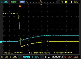
I'm re-measuring with the gate voltage on the yellow channel and the drain voltage on the blue channel of the scope. Notice that the blue channel has a 5V per division scale and the yellow one 1V per division.
 |
| no snubber |
Second lets add a 100nF capacitor from drain to VCC like I did in the previous post.
 |
| "snubber" cap to VCC |
That is with a "snubber" cap to VCC, which arguably is not really a snubber at all.
Finally, lets really add the snubber over the Drain and Source of the mosfet, which means Drain to ground as the Source is directly connected to ground.
 |
| snubber cap across drain-source |
There is still some high frequency noise (~20Mhz) but it has a very low amplitude.
Let's go back to the initial situation, is it really a problem? I guess with the mosfet I'm using (IRF540), not really. It has a Drain Source breakdown voltage of 100V, and the largest peak I notice is 40V. On the other hand that might just go past the breakdown voltage of the LEDs on the LED strip and that is not a good thing either.
A curious thing is that in the non-snubbed circuit the drain voltage goes all the way up to almost 12V and in the snubbed circuit it only goes up to 5V. It looks like the LED strip in combination with the snubber acts as some kind of impedance divider.
If I change the snubber from 100nF to 1uF (10x larger) the peak voltage on the Drain drops to 4V. Changing it to 50nF raises the peak voltage to 6V.
Something to ponder about...
5 comments:
100nF is too much. Something order of magnitude of 1nF seems more appropriate. What you are seeing is that the charging/discharging time of your cap is too large.
Recall that there are three types of oscillation: underdamped, critically damped and underdamped. You are now massively underdamped, so much so that your switching period is probably larger than your rise time.
Another way of looking at it is that your capacitor is effectively an impedance of 1/sC, which corresponds to 1/(2*pi*100k*100n)= ~16 Ohm for 100kHz.
So, what we want is a resistor to dampen the ringing, but it should block current when your transistor is off. You achieve that by placing a small capacitor in series, and that's the basic snubber.
So what values to choose? Look at the frequency of your undamped ringing. Based on your plots you seem to have ~200ns.
C_DS of your transistor will be around 100pF typically, so that means your parasitic inductance can be calculated by T = 2*pi*sqrt(LC).
So the R of your snubber will be sqrt(L/C), and your C of the snubber C = T/R.
In your case I get L~= 10uH (which is a lot, so I might have miscalculated here), which yields R = 330R and C = 680 pF.
Of course, these formulas yield approximated starting values only. Some experimenting is always needed to find the best values.
You are probably be right about the massively underdamped behavior. I'll do some further tests today.
10uH might seem like alot but this is a 5m long wire so who knows...
Joost, do you have any videos of the LED strip dimming? I'm designing something inspired by your design and I think this would be helpful.
KAN: nope, sorry, this was a while ago. There is quite some other information/video out there though on the subject.
Post a Comment